Figure 3 rear panel – Bird Technologies 3128A User Manual
Page 15
3
Table 1-1 Front Panel
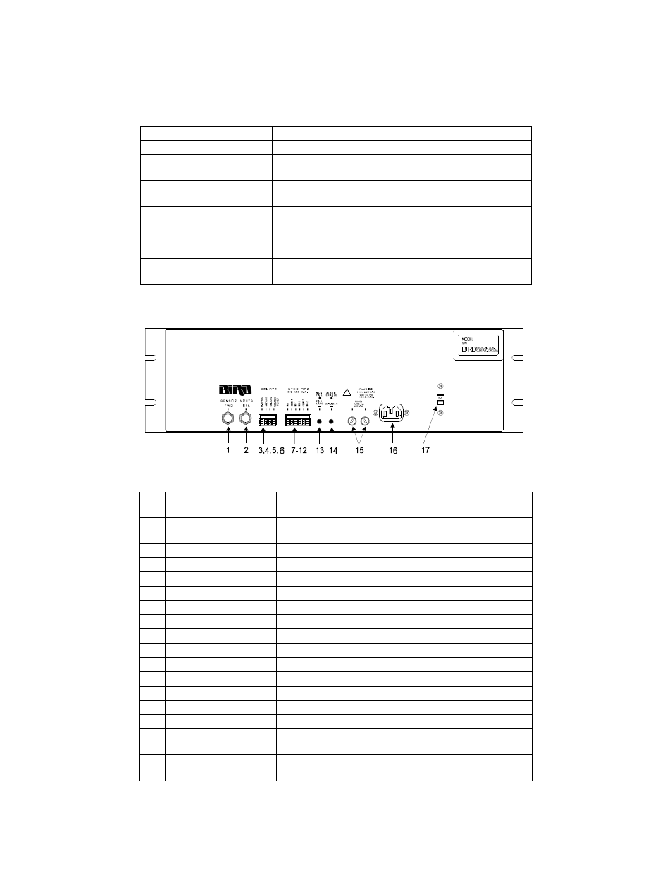
Figure 3 Rear Panel
Table 1-2 Rear Panel
1
Forward Power Meter
Analog Meter Indicating forward power.
2
Reflected Meter
Analog Meter indicating reflected power.
3
Alarm Active LED
Green LED, when illuminated the alarm is active, power
is on.
4
RFL Alarm LED
Red LED, flashes when the reflected power trip level has
been exceeded for more than 50ms.
5
Reset Push-button
Resets the Wattcher to normal operation after the error
condition is corrected
6
View Push-button
Allows for viewing the reflected power trip level during
adjustment.
7
Adjust
Potentiometer providing for adjustment of reflected
power trip level.
1
Forward Sensor
Input Connector
Input connector for forward power sensor cable from
port A of line section.
2
Reflected Sensor
Input Connector
Input connector for reflected power sensor cable from
port B of line section.
3
9-16 VDC
Auxiliary positive (+) DC power connection.
4
Ground
Auxiliary negative (-) power connection.
5
Ground
Remote reset ground connection.
6
Remote Reset
Remote reset connection.
7
NO1
Normally open connection for interlock one.
8
COM1
Common Connection for interlock one.
9
NC1
Normally closed connection for interlock one.
10
NO2
Normally open connection for interlock two.
11
COM2
Common Connection for interlock two.
12
NC2
Normally closed connection for interlock two.
13
Non Fail / Fail Safe
Select switch for non fail-safe or fail-safe mode.
14
Alarm
Alarm enable/disable switch.
15
Fuse
Fuse receptacles for 0.125A, 250v fuses.
16
AC Receptacle
Provides a means of supplying AC line power to
Wattcher.
17
Line Voltage Selector
Switch
Determines line voltage operation.