Chapter 2 theory of operation, General, Alarm condition – Bird Technologies 3128A User Manual
Page 17: Fail-safe/non fail-safe, Element, Figure 4 element schematic, General alarm condition
5
Chapter 2
Theory of Operation
General
The forward power meter acts as a continuous monitor of forward power output. This provides a reference against
the reflected power value enabling determination of power ratios and VSWR.
Alarm Condition
An alarm condition occurs as the result of the reflected power being greater than the reflected power set point for
longer than 50ms. If enabled, an audible alarm will sound.
An alarm condition will also activate the interlock. An active interlock will cause the normally open terminals to
close and the normally closed terminals to open.
Fail-Safe/Non Fail-Safe
In the fail-safe mode an alarm condition will also occur if the Wattcher is not powered. The non fail-safe mode
requires power for an alarm condition.
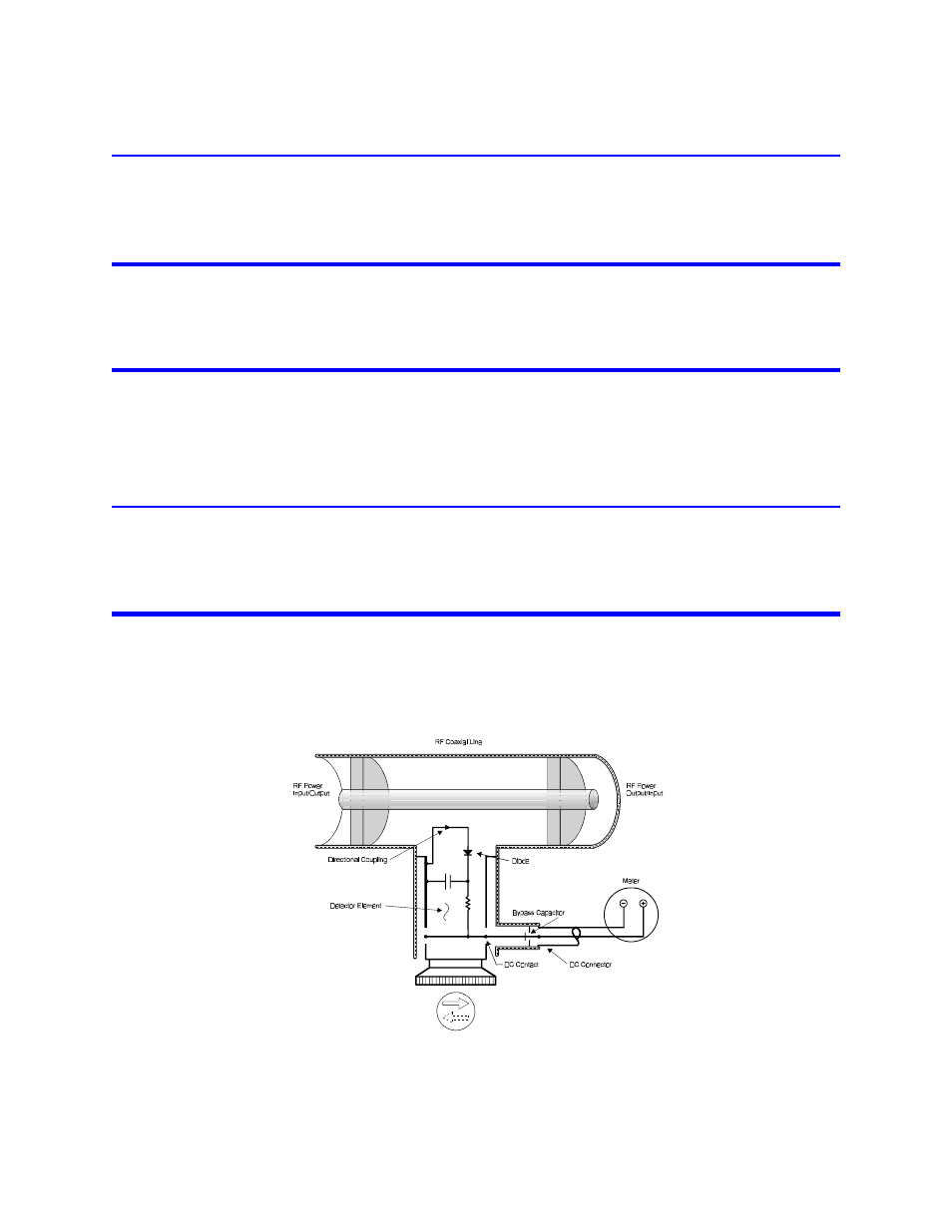
Element
The function of the element is to detect (sense) the forward or reflected RF power in the line section at any given
time. The direction in which the “arrow” on the element cap is oriented indicates the direction in which it is sensing
the RF power flow in the system.
Figure 4 Element Schematic
The forward wave travels and its power flows from the source to the load. It has an RF voltage E
f
and current I
f
in
phase, with E
f
/ I
f
= Z
o
.