Figure 6 unflanged coupling – Bird Technologies 8930 Series User Manual
Page 19
Installation
9
+
NOTE: The swivel flange on the load makes connection
independent of the orientation of the fixed flange on the coaxial
input outer conductor.
y
Insert the bolt sets and tighten evenly all around to transmission
line manufacturer’s recommended torque. Use all of the bolts.
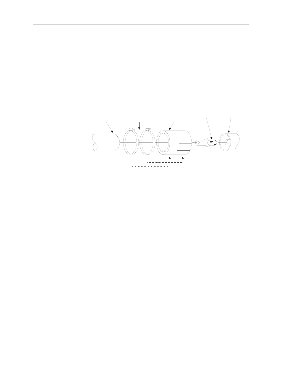
Unflanged Coupling:
To couple the unflanged connector with an
unflanged RF line, use an appropriate coupling kit. Refer to Figure 6
while following the instructions below:
y
Insert the center bullet and bottom it on the midpoint nibs.
y
Position the outer sleeve, with clamping bands, over the input
connector.
y
Set the transmission line snugly against the coupling stops.
y
Position the clamping bands evenly about 3/4” from the ends of
the sleeve.
y
Tighten the clamping bands.
Figure 6
Unflanged
Coupling
RF COAXIAL
LINE
CLAMPING
BANDS
CONNECTOR
SLEEVE
BULLET
LOAD
- SK-4000-TC-Manual (56 pages)
- SK-4000-TC-Datasheet (2 pages)
- SH-36S-Manual (206 pages)
- SH-36S-Datasheet (4 pages)
- SH-36S-PC-Manual (130 pages)
- SH-36S-PC-Datasheet (2 pages)
- SH-36S-PC-Quick Start (2 pages)
- SH-36S-RM-Datasheet (2 pages)
- SA-3600XT-Manual (112 pages)
- SA-3600XT-Datasheet (2 pages)
- AT-500-Manual (73 pages)
- AT-500-Datasheet (2 pages)
- AT-800-Manual (74 pages)
- 89-83F-02-03-Manual (2 pages)
- 89-83F-02-03-Datasheet (1 page)
- 8251 Series-Datasheet (1 page)
- 8251 Series-Manual (30 pages)
- DA10 VHF Series-Datasheet (2 pages)
- DA10 VHF Series-Manual (47 pages)
- 8865SC13-Datasheet (2 pages)
- 8865SC13-Manual (28 pages)
- 8890-300SC13-Manual (28 pages)
- 8921SC13-Manual (28 pages)
- 8931-115SC13-Manual (34 pages)
- BDS-Datasheet (2 pages)
- BDS-Manual (98 pages)
- SCC7 Series-Datasheet (2 pages)
- SCC7 Series-Manual (45 pages)
- MSCC7 Series-Datasheet (2 pages)
- MSCC7 Series-Manual (35 pages)
- SCC8 Series-Datasheet (2 pages)
- SCC8 Series-Manual (47 pages)
- 4020 Series-Datasheet (1 page)
- 4020 Series-Manual (4 pages)
- 4027A Series-Datasheet (2 pages)
- 4027A Series-Manual (6 pages)
- 4027F Series-Datasheet (2 pages)
- 4027F Series-Manual (6 pages)
- 4028 Series-Datasheet (2 pages)
- 4028 Series-Manual (6 pages)
- 7022-Datasheet (4 pages)
- 7022-Manual (27 pages)
- ACM Series-Datasheet (2 pages)
- ACM Series-Manual (40 pages)
- BPME Series-Datasheet (4 pages)