Installation, Maintenance – Bird Technologies 28-88-04B User Manual
Page 7
TXRX Systems Inc. Manual 7-9176-4 06/23/04 Page 3
INSTALLATION
Vari-Notch duplexers should be securely installed
in a dry, vibration-free environment. Attachment of
the cavity shells to a ground bus is recommended
in order to maximize lightning protection. A light-
ning protection device placed in the antenna feed-
line, preceding the duplexer, is recommended.
High quality double shielded coaxial cable termi-
nated with quality connectors (N-type) are recom-
mended for connecting the transmitter and receiver
to the duplexer and are available from TX RX Sys-
tems Inc. It is also important to observe the power
handling ratings of cables in transmit systems.
Mount the duplexer in its permanent operating
position using suitable hardware. Connect the two
transmitters (or transmitter/receiver) and the
antenna feedline to the duplexer making sure to
connect the correct equipment to the correct port.
Labels are affixed next to each port (port labels) to
help you make the right connections. In addition, a
specification tag will be found in a plastic bag
attached to one of the tuning rods. The frequency
that each cavity group is tuned to will appear on
either the port labels or the specification tag. The
duplexer is now ready for normal operation. No tun-
ing is required if the frequencies (high frequency
and low frequency) found on the port labels/specifi-
cation tag matches the actual operating frequen-
cies.
MAINTENANCE
No special maintenance is required. Vari-Notch
duplexers are passive devices of rugged electrical
and mechanical design. They are tuned at the fac-
tor y for the original design requirements and
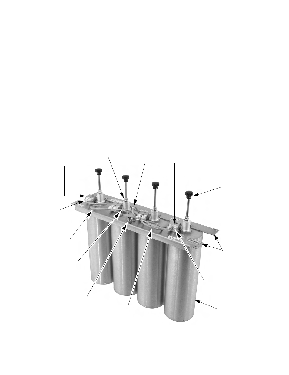
Equipment
Port
1/4” Shaft
Locking Nut
Tuning
Rod
Loop
Assembly
Variable
Capacitor
Equipment
Port
Mounting
Bar
Figure 2: Typical four-cavity Vari-Notch Duplexer.
Interconnect
Cable
Antenna
Port
Antenna
Cable
Antenna
Cable
Interconnect
Cable
Cavity
Resonator