Unpacking – Bird Technologies 28-88-04B User Manual
Page 6
TXRX Systems Inc. Manual 7-9176-4 06/23/04 Page
2
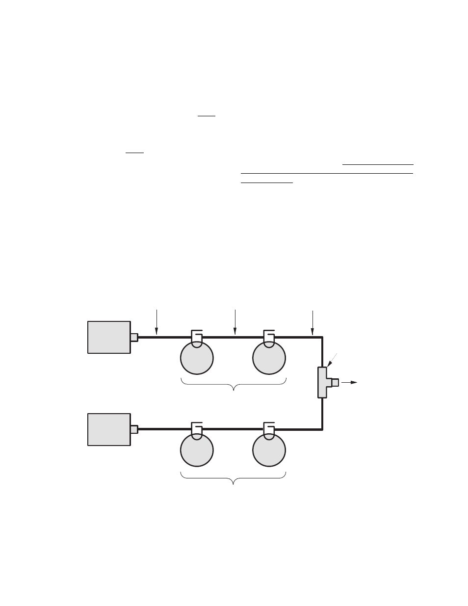
Resonant cavity filters are the basic building blocks
of the system. Also important, are the interconnect
cables between each filter which have cut length's
equivalent to either 1/4
λ or 3/4 λ of that channels
pass frequency. The exception is the antenna cable
that couples each channels final filter to the
antenna port, which is cut to 1/2
λ of the other (or
remaining) channels pass frequency. This effec-
tively places a relatively large impedance in parallel
with the antenna, insuring a good impedance
match between the other (or remaining) channel
and the antenna. This technique of impedance
matching allows both channels to be connected to
the same antenna with very little loss due to mis-
matching. The antenna cables are permanently
soldered and crimped to the antenna junction. The
combination of the antenna junction and the
attached antenna cables is referred to as an
"Antenna Junction Assembly".
Figure 1 shows the functional block diagram of a
typical four-cavity Vari-Notch duplexer system. Six
and eight cavity systems are similar except for the
extra filters in each channel. The photograph
shown in Figure 2 is the front view of a typical four-
cavity Vari-Notch duplexer. Each of the physical
components in the system is labeled with the field
adjustable parts shown in emboldened italics.
UNPACKING
Care should be used when removing the duplexer
from it's shipping container to avoid unnecessary
damage. It is impor tant to visually inspect the
duplexer for any shipping damage as soon as pos-
sible after taking delivery. It is the customers
responsibility to file any necessary damage claims
with the carrier.
Vari-Notch duplexers are rugged devices but may
become detuned if jostled or dented during ship-
ping. The most easily damaged par ts of the
duplexer are the tuning rods. These rods are
marked where they exit from the locking nut with a
dab of red varnish or other color/type of paint. If
this seal appears to be broken it may indicate that
the system has been detuned in transit.
High
Frequency
Equipment
RG214 or RG142
Double-Shielded Cable
(Supplied by customer)
To
Antenna
TYPICAL FOUR CAVITY VARI-NOTCH FILTER
Interconnect Cable
(1/4
λ or 3/4 λ of this)
(channels pass freq.)
Antenna Cable
(1/2
λ of the other)
(channels pass freq.)
Vari-
Notch
Filter
Vari-
Notch
Filter
Vari-
Notch
Filter
Vari-
Notch
Filter
Low
Frequency
Equipment
Antenna
Junction
Passband tuned to high frequency
Rejection notch tuned to low frequency
Passband tuned to low frequency
Rejection notch tuned to high frequency
Figure 1: Block diagram of typical four-cavity Vari-Notch Duplexers.