Bird Technologies 28-88-04B User Manual
Page 13
TXRX Systems Inc. Manual 7-9176-4 06/23/04 Page 9
20. Repeat step 17 and 18 for the remaining chan-
nel (cables and equipment stay connected
where they are). Remember to replace the
small screws or rubber buttons on the side of
the loop assemblies.
21. With the tuning completed, reconnect the
equipment cables and antenna feedline. Test
the system for proper operation.
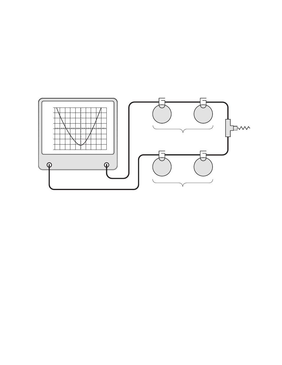
Figure 7: Equipment setup for fine tuning the rejection notch of each channel.
GENERATE
OUTPUT
ANALYZER
INPUT
dBm
-30
-40
-50
-60
-70
-80
-90
-100
-110
30
0
10
300
dBm
dB ATT
GEN
dBM
MSEC
KHz RES
KHz/DIV
50
MHz
50
Ω
Load
Vari-
Notch
Filter
Vari-
Notch
Filter
Vari-
Notch
Filter
Vari-
Notch
Filter
High Frequency Pass Channel
Reject the Low Frequency Channel
Low Frequency Pass Channel
Reject the High Frequency Channel