Bird Technologies 28-88-04B User Manual
Page 12
TXRX Systems Inc. Manual 7-9176-4 06/23/04 Page
8
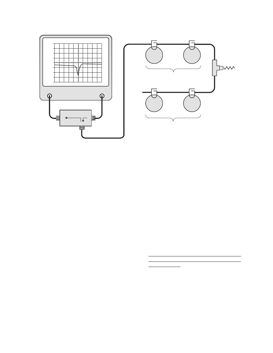
13. The rejection notch for each of the channels
must be fine tuned next.
14. Terminate the antenna connector with a 50
ohm load. Connect the output of the tracking
generator to the equipment port of one of the
duplexer channels and the spectrum analyzer
input to the equipment port of the remaining
channel as shown in Figure 7.
15. Set-up the analyzer / generator to sweep
across the rejection notch frequency of the
channel being tuned. The center of the display
should be set to the desired center frequency
of the rejection notch being adjusted. Set the
vertical scale of the analyzer / generator to 10
dB/div.
Keep in mind that the high frequency channel
has its rejection notch set to reject the low fre-
quency signal and vice-versa for the rejection
notch of the low frequency channel.
16. Insure that the IFR A-7550 menu's are set as
follows:
DISPLAY - line
MODE - live
FILTER - none
SETUP - 50 ohm/dBm/gen1
17. Set the analyzer's attenuation control so that
the "peak" or lowest value on the rejection
notch is displayed. The "peak" should be
around -100 dB depending upon which model
of duplexer you are tuning.
18. The cavities rejection notches are adjusted (for
maximum rejection) by gently turning the vari-
able capacitors in the loop assemblies. Move
between filters as needed.
Because of the filters sensitivity to tool contact,
an insulated tuning tool must be used to make
the adjustment. Access to the capacitors is
obtained by removing the small screw or rub-
ber button on the side of the loop assemblies.
19. Adjust the rejection notch of the remaining cav-
ities by changing the sweep frequency of the
analyzer / generator to match the new rejection
notch frequency. The equipment stays con-
nected as it is.
GENERATE
OUTPUT
ANALYZER
INPUT
dBm
40
30
20
10
0
-10
-20
-40
-40
40
0
10
300
dBm
dB ATT
GEN
dBM
MSEC
KHz RES
KHz/DIV
500
MHz
Load
So
ur
ce
R
e
fl
e
c
te
d
50
Ω
Load
Vari-
Notch
Filter
Vari-
Notch
Filter
Vari-
Notch
Filter
Vari-
Notch
Filter
High Frequency Pass Channel
Reject the Low Frequency Channel
Low Frequency Pass Channel
Reject the High Frequency Channel
RLB - 150 BRIDGE
(RLB)
Figure 6: Equipment setup for fine tuning the passband of each channel.