Bendix Commercial Vehicle Systems ACom Diagnostics V.5.9 User Manual
Page 6
6
Figure 6
Install program displays that the program has been
installed on the computer.
Figure 7
Uninstall ACom
™
Diagnostics
If there is a need to uninstall ACom
™
diagnostics it is
recommended that the user: click on the “Start” button
on the task bar, Program, fi nd Bendix, ECU installer,
choose “uninstall”.
Help
Provides you access to the help fi les available for
ACom
™
diagnostics. These fi les will provide you
with information about features / operation of ACom
™
diagnostics. To access the Help contents, select the
Help icon from any screen or the main menu.
Demo Mode
The demo mode allows the user to get familiar with the
software without having to be connected to a vehicle and
an ECU. The information shown is for demonstration
purposes only, and does not necessarily refl ect actual
conditions.
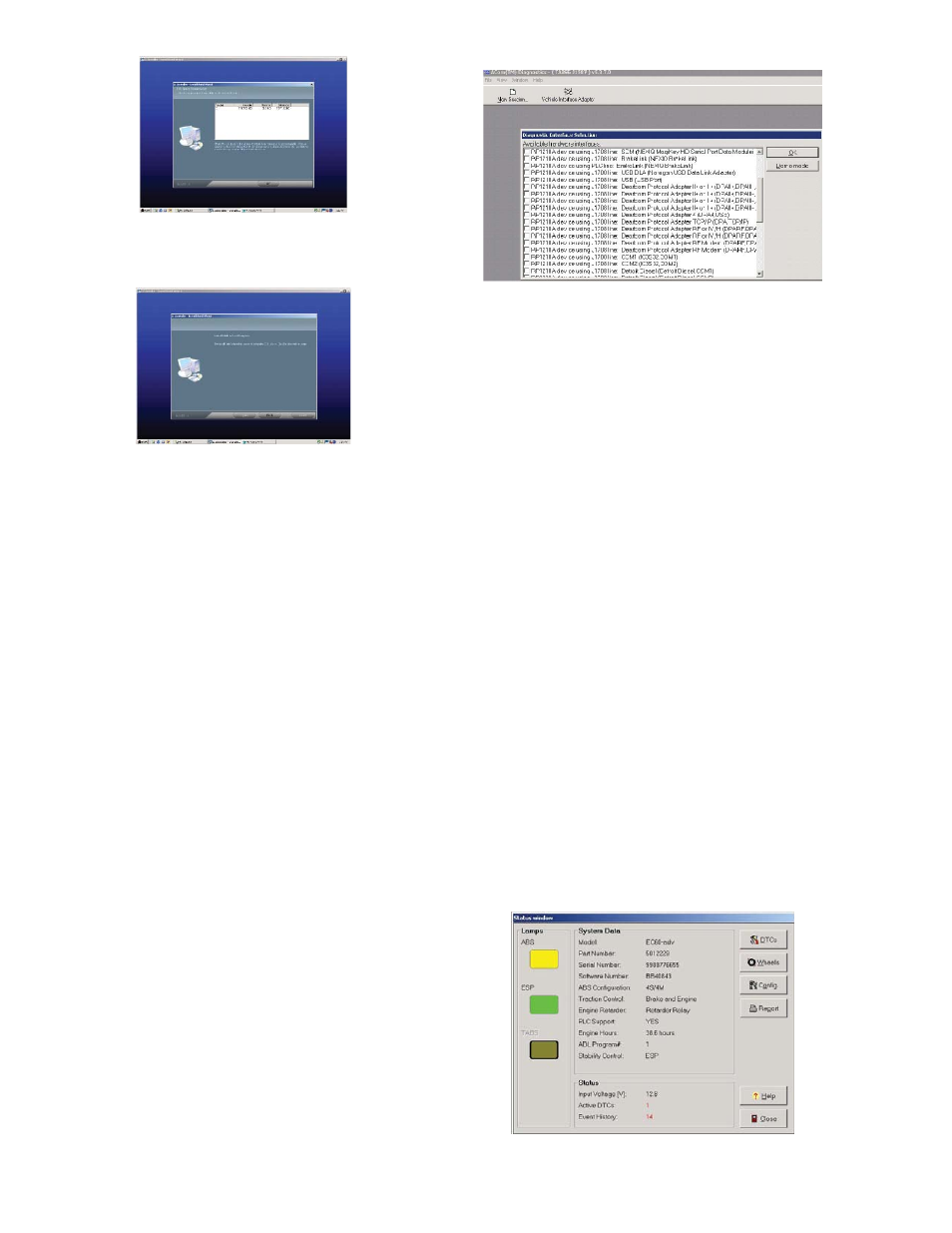
Hardware Adapter Selection
The user will be prompted to select the adapter they are
using for communications. The adapter selection list is
generated from the drivers installed on the computer for
the RP1210B devices. Additionally, there is a vehicle
interface selection button which brings up the available
adapter selection list.
Figure 8
Functions of Software
Once communication has been established the program
displays the Status screen.
The user will now be able to view the following screens
for all ECUs
• ECU
Status
• Diagnostic
Trouble
Codes
• Wheel
speed
• Confi guration
• Component
test
• Installation
test
Additional screen functions provided based on ECU
type
•
Stability Sensors (EC-60
™
Advanced)
• Pressures
(EC-60
™
Advanced)
•
Scratch Pad (Trailer ABS ECUs)
• ADL
(EC-60
™
and TABS-6)
•
Dyno Mode (EC-60
™
)
NOTE: EC-17 is only supported with ECU status, DTC
and Confi guration screens.
Status Screen
The status screen provides an overview of the current
ABS system. Not all information is supported or available
from all the ECUs, in such a case the data fi eld will
display not available (NA). Information displayed will be
read once at the opening of the screen.
Input voltage, active faults and in-cab lamps will be
continuously updated.
Figure 9