Bendix Commercial Vehicle Systems ACom Diagnostics V.5.9 User Manual
Page 11
11
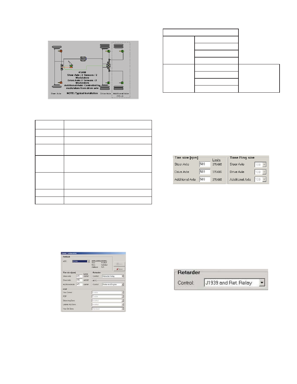
Confi guration Diagram
The diagram will refl ect the typical ABS installation for
the confi guration read from the ABS ECU.
Figure 27
Control Buttons
Modify
Launches the Confi guration Modifi cation screen
Self Confi g
Performs a self confi guration of the ABS System
Broadcast
Launches the Broadcast options
AUX I/O
Launches a window displaying the status of the auxiliary
inputs / outputs
Calibrate
(Advanced
Only)
Launches the sensor calibration services the Advanced
ESP sensors require.
ESP Parameters
(Advanced
Only)
Launches the ESP parameter information. Once the win-
dow has been launched a save parameter option becomes
available.
Help
Launches Help system
Close
Closes the confi guration screen
Modify Button
The modify button opens the change confi guration
window allowing the following confi guration information
to be changed: Antilock number of sensors and
modulators, Tire size, Retarder, ATC.
NOTE: ESP parameters are read only.
Figure 28
Antilock
This fi eld will show the available sensor / modulator
combinations for the ABS ECU. Trailer applications
will display the control method along with the sensor
/ modulator combination. Consult Bendix if you are
unsure how to correctly confi gure these parameters.
Possible confi gurations are listed below.
Confi guration
Tractor
4S / 4M
6S / 4M
6S / 5M
6S / 6M
Trailer
4S / 3M
Control will be
either axle or side
4S / 2M
2S / 1M
2S/ 2M
Tire Size
Tire size is adjustable to within the limits available for the
ABS ECU. Consult the tire manufacturer specifi cations
for these values. Additionally, the ECU will set a DTC
if the tire sizes are out of range. NOTE: The program
assumes that a 100-tooth tone ring is being used.
The tire size read back from the ECU may not be
what the user selected because of how the tool
scales the values.
Figure 29
NOTE: ACom Diagnostics 5.3 and up allow the tone
ring to be changed for the TABS-6 ONLY.
Retarder
The available control methods are typically:
Not Controlled – No retarder control for this
confi guration
Retarder Relay – Retarder controlled by a retarder
disable relay
Retarder Data link – Retarder controlled by J1939
communications
Figure 30
ATC
The available control methods are:
No Control – No traction control present or enabled
Brake – Brake control is automatically activated when
drive wheel(s) on one side of the vehicle are spinning,
which typically occurs on a split-coeffi cient surface
(such as asphalt and ice). The traction system will
then lightly apply the brake to the drive wheel(s) that
are spinning. The vehicle differential will then drive the
wheels on the other side of the vehicle. Brake control
is available at vehicle speeds up to 25 MPH.