Bendix Commercial Vehicle Systems SMARTIRE TPMS OPERATORS MANUAL User Manual
Page 40
40
6.0 SYSTEM INSTALLATION: ELECTRICAL
6.1 TOOLS REQUIRED
Installing the Receiver
1. Two ¼ -20 (M6X1) flange head cap screws with lock washers and nuts
2. Wrenches for tightening cap screw
Installing the Display
1. Power drill & 2 1/8" (54mm) hole saw
2. 1 Ring terminal 22-18 AWG, stud size 8-10 for grounding*
Installing the Antennas
1. Power drill & bits *
2. Silicone
sealant
*
3. 1" open ended wrench or crescent wrench
4. 2 small self-tapping screws for antenna bracket to fit 3/16" holes*
5. 15 medium sized, black cable ties
6. Electrical tape
* Tool may not be required
6.2 GETTING STARTED
Like all integrated systems, the installation location of each component is dependant upon the
location of the other components in the system. As such, it is best to select the overall location of
each component before starting.
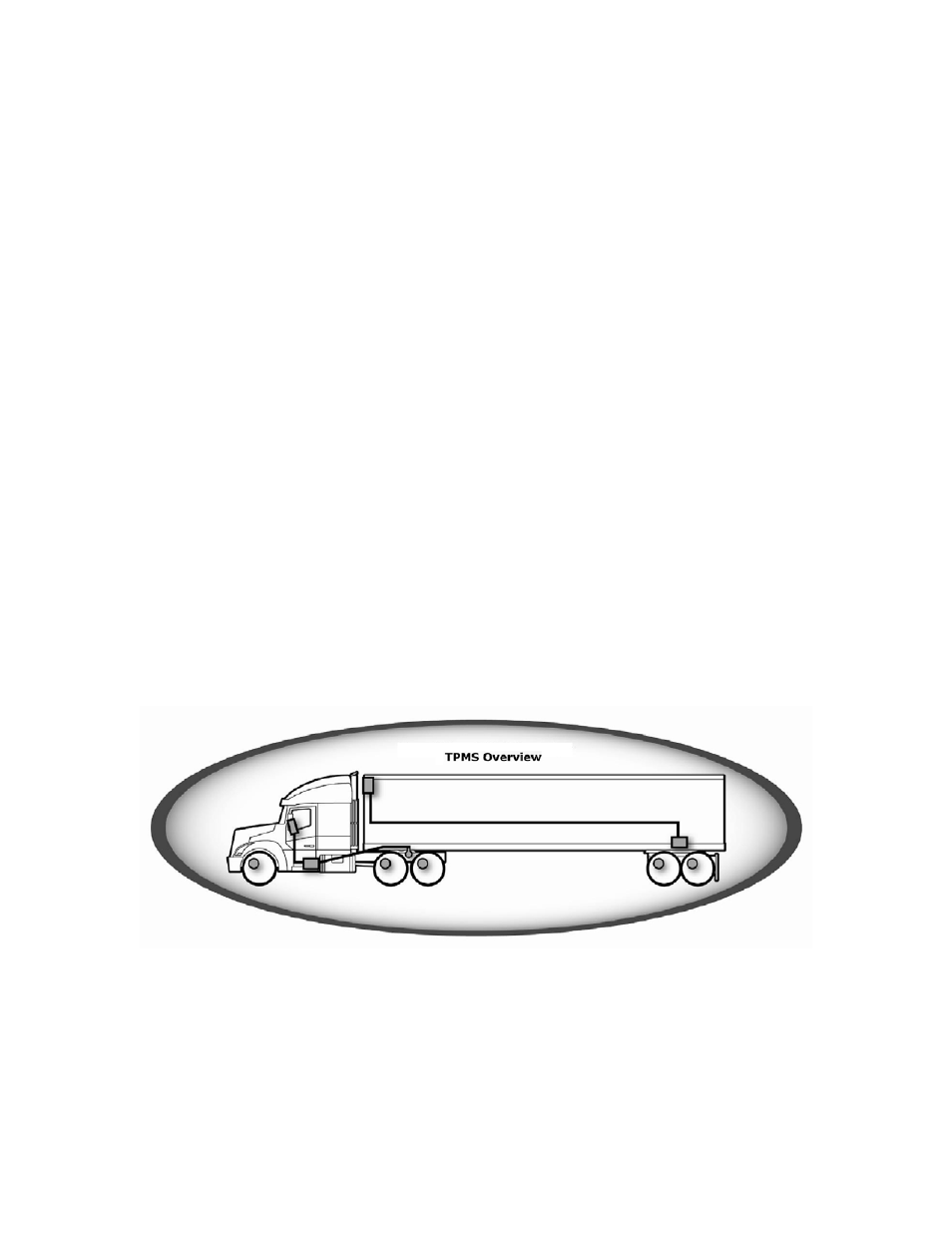
The following diagrams show common vehicle system configurations:
Truck with Trailer
1. Dash-mounted display connects to Wireless Gateway Receiver.
2. Wireless Gateway Receiver connects to underside of vehicle.
3. Antenna at rear axle(s) connects to Wireless Gateway Receiver.
4. 2
nd
Wireless Gateway Receiver mounts to the trailer at its rear axle(s).
5. Trailer lamp mounts within view of the driver and connects to the Wireless Gateway
Receiver.
6. Sensors mount to the wheels.