Operation – Bendix Commercial Vehicle Systems AD-SP SYSTEM PURGE AIR DRYER 10/04 User Manual
Page 4
4
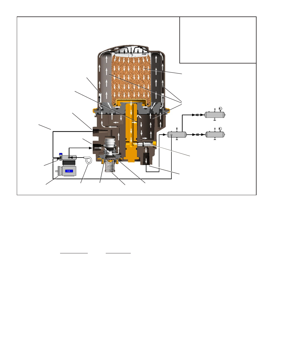
FIGURE 2 -
BENDIX
®
AD-IP
®
INTEGRAL PURGE AIR DRYER CHARGE CYCLE
OPERATION
GENERAL
Note: Unless otherwise stated in this manual, the Bendix
®
AD-IP
®
air dryer refers to both the standard and Bendix
®
AD-IP
®
PuraGuard
®
oil coalescing air dryer. The AD-IP air
dryer alternates between two operational modes or “cycles”
during operation: the Charge Cycle and the Purge Cycle.
The following description of operation is separated into
these “cycles” of operation.
CHARGE CYCLE
(Refer to Figure 2)
When the compressor is loaded (compressing air)
compressed air — along with oil, oil vapor, water and water
vapor — flows through the compressor discharge line to the
supply port of the air dryer body.
As air travels through the end cover assembly, its direction
of flow changes several times, reducing the temperature,
causing contaminants to condense and drop to the bottom
or sump of the air dryer end cover.
After exiting the end cover, the air flows into the desiccant
cartridge. Once in the desiccant cartridge the air first flows
through an oil separator, located between the outer and
inner shells of the cartridge. The separator removes water
in liquid form as well as liquid oil and solid contaminants.
Air, along with the remaining water vapor, is further cooled
as it exits the oil separator and continues to flow upward
between the outer and inner shells. Upon reaching the top
of the cartridge the air reverses its direction of flow and
enters the desiccant drying bed. Air flowing down through
the column of desiccant becomes progressively drier as
water vapor adheres to the desiccant material in a process
known as “ADSORPTION.” The desiccant cartridge using
the adsorption process typically removes most of the water
vapor from the pressurized air.
Dry air exits the bottom of the desiccant cartridge and flows
through the center of the bolt used to secure the cartridge
to the end cover. Air flows down the center of the desiccant
cartridge bolt, through a cross drilled passage and exits
the air dryer delivery port through the delivery check valve.
DESICCANT
BED
DELIVERY
CHECK VALVE
PURGE
VOLUME
DISCHARGE
PORT
EXHAUST
PURGE
VALVE
TURBO
CUT-OFF VALVE
ENGINE
TURBO
COMPRESSOR
GOVERNOR
PURGE
CONTROL
LINE
CONTROL
PORT
SUPPLY
PORT
OIL
SEPARATOR
PURGE
ORIFICE
Note 1:
The Bendix
®
AD-IP
®
air dryer and reservoir
system purge piston has a purge control
channel drain. This allows any condensation
in this area to flow past a diaphragm in the
top of the purge piston and out through a
channel in the middle of the central bolt of
the purge assembly to be drained. During
the purge cycle this drain is closed.