Bendix Commercial Vehicle Systems AD-SP SYSTEM PURGE AIR DRYER 10/04 User Manual
Page 12
12
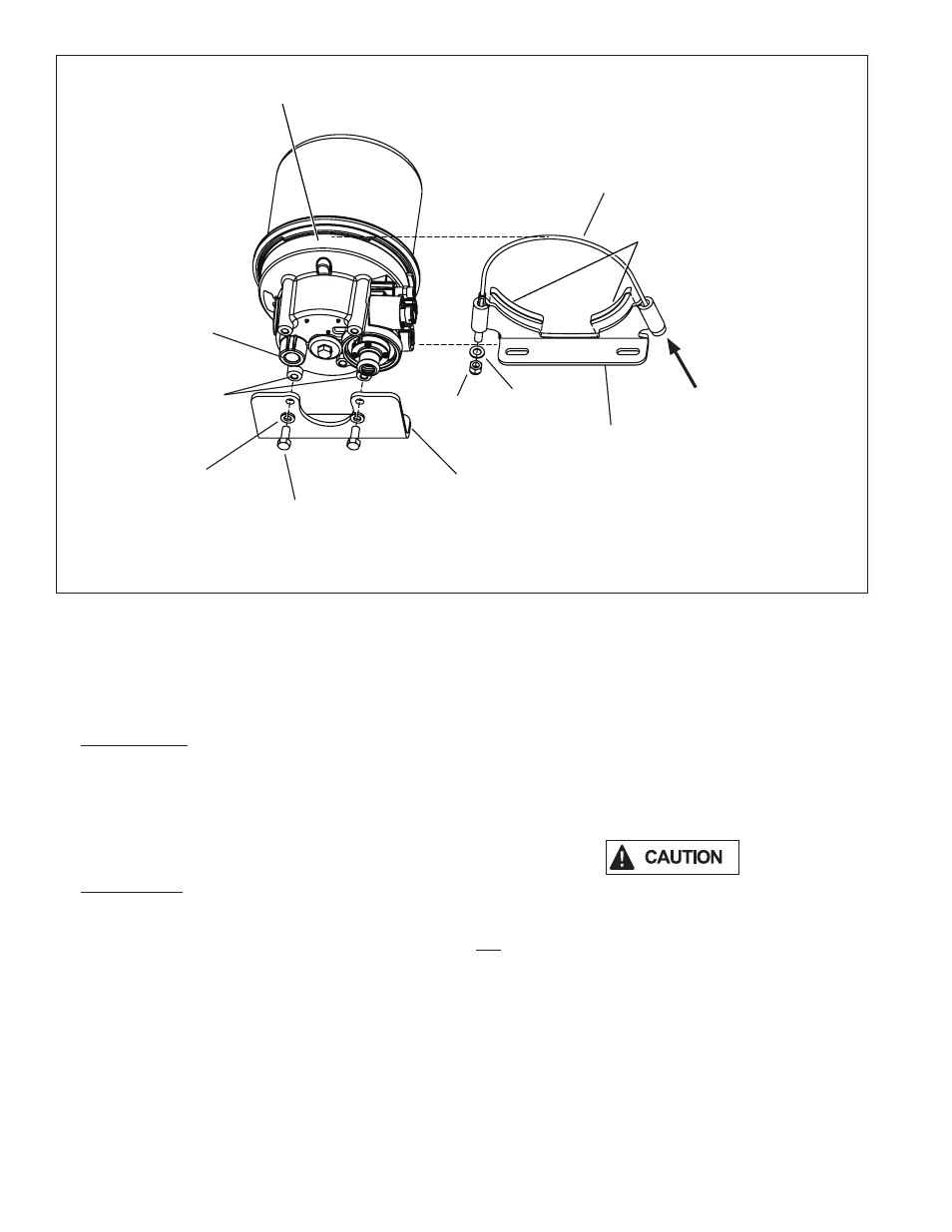
FIGURE 10 -
BENDIX
®
AD-IP
®
AIR DRYER CABLE BRACKET INSTALLATION
There are two types of upper mounting brackets; saddle
type (shown in Figure 8), and cable type (shown in Figure
10). Refer to the appropriate figure for the type of air dryer
being serviced.
6. Saddle Bracket: Mark the relationship of the saddle
bracket (5) to the end cover assembly (6). Remove
the 5/16” cap screw (1) and sleeve nut (3) securing
the upper mounting strap (4) to the saddle bracket (5).
Earlier models used a washer and nut in place of the
sleeve nut (3). Remove the upper mounting strap (4)
from the end cover assembly (6). Refer to Figure 8.
Cable Bracket: Mark the relationship of the upper
bracket (31) to the air dryer end cover (6). Remove the
locknut (34) and washer (35) from the cable assembly.
Remove the cable assembly (32) from the upper
bracket. Remove the upper bracket (31) and isolators
(33).
7. Mark the relationship of the lower bracket (9) to the end
cover assembly (6). Remove the two 3/8” end cover cap
screws (7) and two washers (8) that retain the lower
mounting bracket (9) to the end cover (6).
DISASSEMBLY
The following disassembly and assembly procedure is
presented for reference purposes and presupposes that
a major rebuild of the Bendix
®
AD-IP
®
air dryer is being
undertaken. The replacement parts and maintenance kits
available generally do not require full disassembly. The
instructions provided with these parts and kits should be
followed in lieu of the instructions presented here. Refer
to Figures 8 and 9 during disassembly.
While performing service on the AD-IP air dryer, it is
recommended that a clamping device (vise, C-clamp, etc.)
not be used to hold any die cast aluminum component as
damage may result. To hold the end cover, install a pipe
nipple in the supply port and clamp the nipple into a vise.
1. Using an adjustable, or socket wrench, loosen the
desiccant cartridge bolt (10), then separate the
desiccant cartridge (11) from the end cover (6). Pull
the desiccant cartridge bolt out of the end cover (6).
LOWER BRACKET
MOUNTING
HOLES
INSTALL CABLE
ASSEMBLY IN THIS AREA
DELIVERY
PORT
INSERT CABLE
ASSEMBLY IN UPPER
BRACKET WING HOLE AS
SHOWN
7
8
9
31
32
33
34
35