Bendix Commercial Vehicle Systems AD-SP SYSTEM PURGE AIR DRYER 10/04 User Manual
Page 16
16
CONNECTING THE AIR LINES
PURGE CONTROL LINE
1. Install a purge control air line having a minimum
inside diameter of 3/16 inches between the Bendix
®
AD-IP
®
air dryer end cover control port and an unused
unloader port on the governor. The control line must
be connected directly to the governor and not in series
with automatic drain valves, lubrication systems, etc.
2. The control line should slope downward to the end
cover without forming sharp bends or “dips”.
COMPRESSOR DISCHARGE LINE
GENERAL:
Refer to Appendix A, Table A for recommended discharge
line lengths and sizes for various vehicle applications and
vocations.
PURGE EXHAUST LINE
1. If it is necessary to direct AD-IP air dryer discharge
contaminants away from vehicle components it will be
necessary to purchase a special exhaust cover for the
AD-IP air dryer (Pc. No. 112609) and install on the unit.
A 1 inch (25.4 mm) I.D. hose can be clamped on the
special AD-IP air dryer exhaust cover.
WIRING THE HEATER & THERMOSTAT (Refer to
FIGURE 7)
1. The air dryer is available with either a 12 or 24 volt
heater which uses 90 watts of power. Determine the
vehicle’s electrical system voltage and make certain
that the air dryer that is to be installed contains the same
voltage heater. The air dryer’s part number can be used
to determine the air dryers heater voltage requirement.
The heater voltage can also be identified by the color
of the heater assembly connector as described in the
table below.
Air Dryer Heater
Air Dryer Connector
Voltage
Identification
12 Volts
White (No other markings)
24 Volts
Gray, or White w/Red Dot
2. A two lead, 24 inch, wire harness with attached weather
resistant connector is needed for the installation of an
AD-IP air dryer. Connect one of the two leads of the
wire harness to the engine kill or ignition switch. The
remaining lead of the wire harness must be connected
to a good vehicle ground (not to the air dryer or its
mounting bracket). A fuse must be installed in the power
carrying wire; install a 10 amp fuse for 12 volt heaters
and a 5 amp fuse for 24 volt heaters.
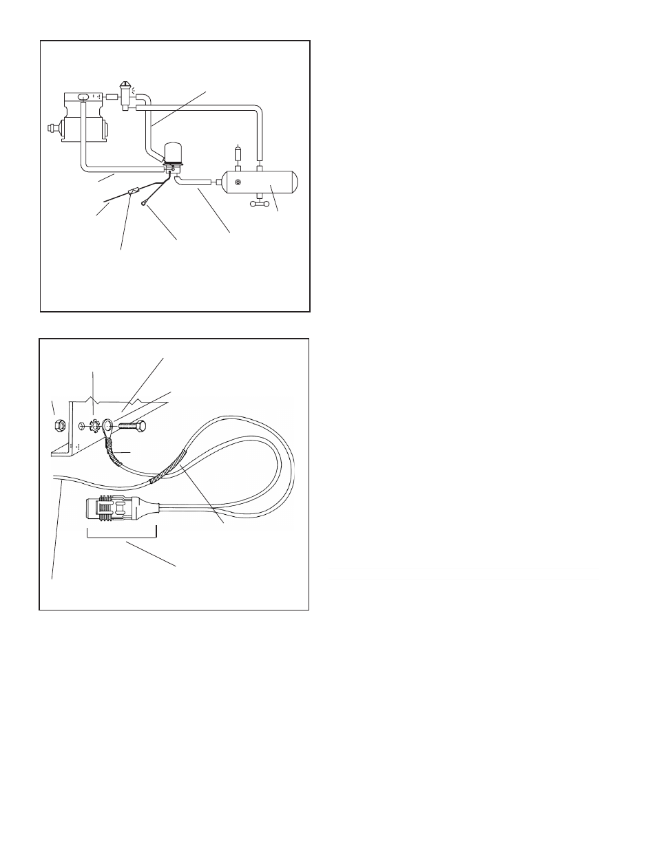
FIGURE 12 -
WIRING - REMOTE POWER & LOCAL
GROUND
GROUND
LEAD
1/4” or 3/8”
EYELET
FRAME RAIL
STAR WASHER
NUT
14 GAUGE POWER WIRE
FROM VEHICLE
WIRE HARNESS
CONNECTOR
(TO AIR DRYER)
WEATHERPROOF
POWER LEAD
SPLICE
SUPPLY RES.
GOVERNOR
PURGE CONTROL
LINE TO
CON PORT
HEATER &
THERMOSTAT
LEAD TO
GROUND
DELIVERY LINE
FROM
DEL PORT
ON AD-IP
®
AIR
DRYER
AD-IP
®
AIR
DRYER
FUSE
10 AMP - 12 VOLT
5 AMP - 24 VOLT
HEATER &
THERMOSTAT
LEAD TO
IGNITION
SWITCH
DISCHARGE
LINE TO
SUP
PORT
FIGURE 11 -
BENDIX
®
AD-IP
®
AIR DRYER INSTALLATION