Rockwell Automation T3122 ICS Regent Processor Modules User Manual
Page 12
Processor Modules (T3110, 11, 12, 20, 21, and 22)
1 2
Industrial Control Services
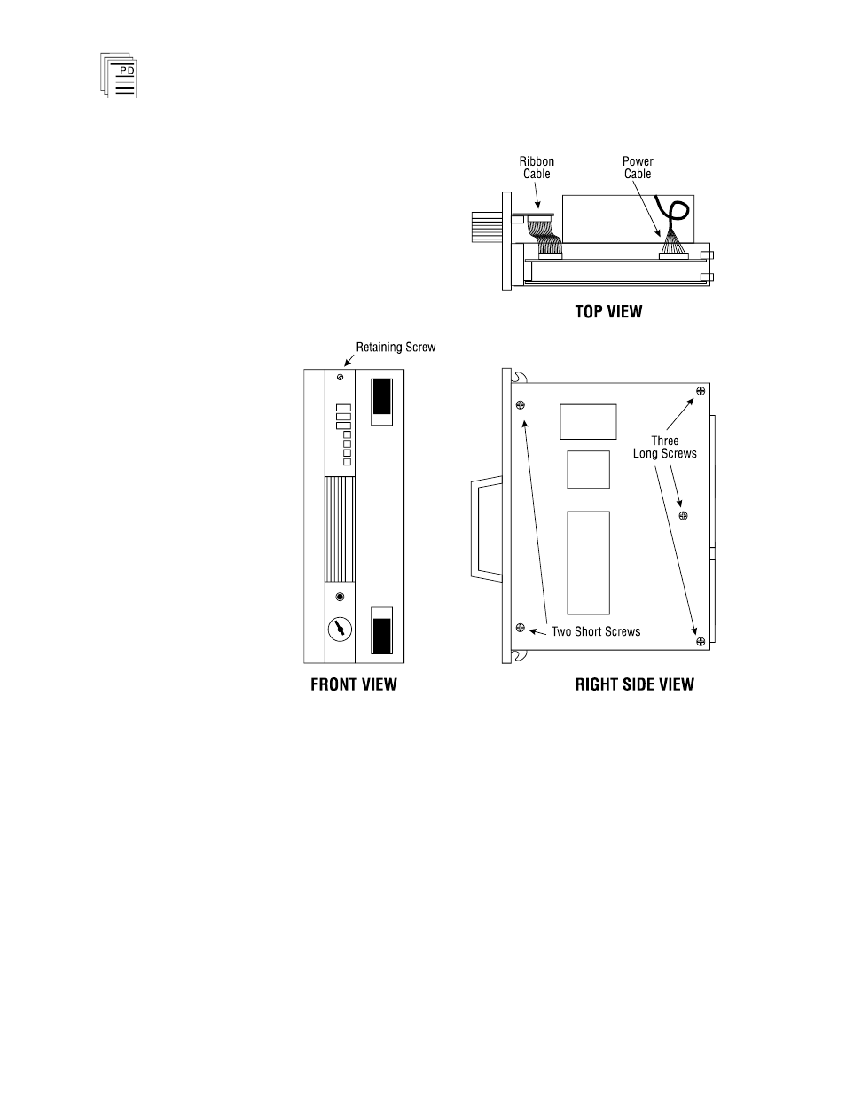
Figure 5. Processor Module Disassembly.
Loosen and remove the two screws securing the circuit board
assembly to the metal frame. Remove the three cylindrical
metal spacers and place them to one side. Lift the two circuit
boards from the metal frame.
The top circuit board (with the Motorola 68000 processor and
two EPROMs in blue chip sockets) is the main processor
board. The bottom circuit board (with a single EPROM in a
blue chip socket) is the I/O processor board. Both boards are
connected by a wide ribbon cable. There is no need to remove
This manual is related to the following products: