Msr12t – Rockwell Automation 440R MSR12T Minotaur Safety Relay User Manual
Page 2
(b)
Verriegelungs- oder NOT-AUS-Kontrolle
mit Überwachung externer Relais mit
automatischer Rückstellung (ohne
Überwachung). /Interrupteur interverrouillé
ou commande d’arrêt d’urgence (E-STOP)
comprenant le contrôle de relais externes
avec Réarmement Automatique (non
contrôlé).
(c)
SPANNUNGSVERSORGUNG /
ALIMENTATION
(d)
Verriegelungsschalter oder NOT-AUS /
Interrupteur d’interverrouillage ou arrêt
d’urgence.
(e)
Die Spannungsversorgung muß den
Vorschriften der EN 60204-1
entsprechen. Klemme A2 muß an die
Seite des Steuerkreises angeschlossen
werden, die mit dem Schutzleiter
verbunden ist.
ZUR BEACHTUNG: Die Ausgänge sind
durch eine externe Sicherung zu
schützen.
La tension d’alimentation doit être conforme
aux spécifications d’EN 60204-1. La borne
A2 doit être connectée au côté du circuit de
commande qui est relié au conducteur de
protection.
REMARQUE : les sorties doivent être
protégées par un fusible extérieur.
(f)
Überbrücken, wenn externe
Relaisüberwachung oder -rückstellung
nicht erforderlich ist. /Relier lorsque le
contrôle ou le réarmement des relais externes
n’est pas requis.
(g)
Rückstellung (ohne Überwachung), falls
gewünscht. / Réarmement (non contrôlé),
lorsqu’il est spécifié.
5
(a)
In Einbaugehäuse nach mind. IP 54
montieren / Monter dans un coffret
conforme au minimum à la norme IP 54
(b)
Austauschsicherung, /
Fusible de rechange
3
(b)
SCHUTZKREIS / CIRCUIT DE PROTECTION
(c)
ÜBERWACHUNGSKREIS /CIRCUIT DE
CONTROLE
(d)
TEST/RÜCKSTELLUNG /
TESTER / REARMER
4
(a)
Deckel wieder aufsetzen /
Remettre le couvercle sans forcer
(b)
Spannung anschließen. Vor
Inbetriebnahme auf korrekte
Funktion überprüfen.
/
Connectez l'alimentation - Contrôlez le
bon fonctionnement des sécurités
avant la mise en service pour la protection
des opérateurs.
6
6
5
3
4
(a)
Mount in enclosure to a min of IP 54.
500 mAT
(b)
Fuse replacement
(a)
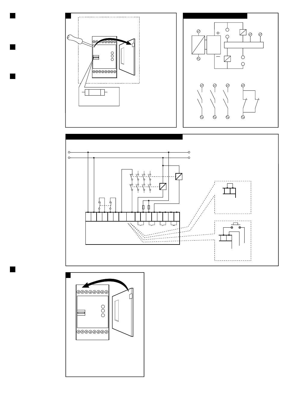
Wiring example / Anschlußbeispiele / Exemples de câblage
(b)
Interlock Switch or E-STOP control with Monitoring of External Relays with Auto Reset (not monitored).
(e)
The supply voltage must meet the requirements of EN 60204-1. Terminal A2 must be connected
to that side of the control circuit which is connected to the protective conductor.
NOTE: Outputs should be protected by an external fuse.
(a)
Replace Cover.
Connect power - Check
operation before
allowing operator use.
X1
S23
S24
S13
S14
K1
K2
13
14
(d)
RESET
X2
23
24
33
34
41
K1
K2
K1
K1
K1
K2
K2
K2
42
(c)
MONITORING CIRCUIT
(b)
PROTECTION
CIRCUIT
~
=
A1 A2
(c)
SUPPLY
SUPPLY
S13 S14 S23 S24 X1
X2
OUTPUTS
SUPPLY CH1
CH2
K1
K2
(d)
Interlock Switch
or E-STOP
MSR12T
230VAC or 110VAC or 24V AC/DC
13 14 23 24 33 34 41 42
K1
K2
(f)
Link when external
relay monitoring or reset is
not required.
X1 X2
(g)
Reset (non monitored)
if required.
X1 X2
(a)
Internal Circuit / Innenschaltibild / Circuit interne