Selecting and sizing snubber braking resistors – Rockwell Automation M3575TL Snubber Braking Kits, AC Drives, Enclosed User Manual
Page 18
18
Enclosed Resistor Modules, Enclosed Transistor Modules
Selecting and Sizing Snubber Braking Resistors
Continuous duty snubber braking resistors must be selected for the transistor switching circuit versions of the
Braking unit.
Use the following procedure to select the snubber resistors:
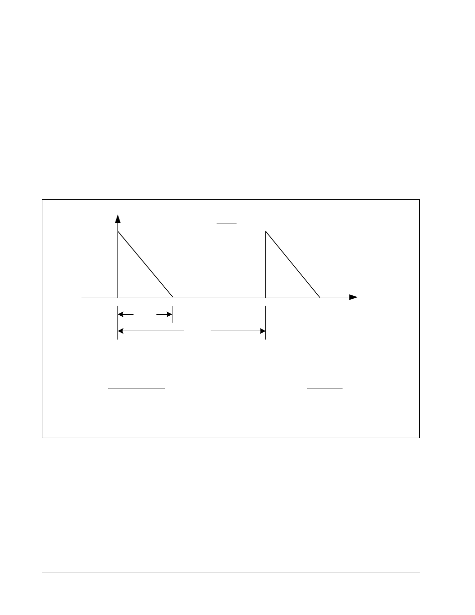
Step 1. Calculate the regenerated power (P
ave
) from the load and the pattern of operation. See figure 9.
P
ave
= 0.5 x P
p
x t/T
Where: P
p
= Peak Power
t = Rise/Fall Time
T = Period
Step 2. Calculate the power dissipation of the resistor (P
d
) by deducting 15% of the motor’s rated output
(energy dissipation by the machine and the motor) from the regenerated power (P
ave
).
Step 3. Use the following formula to determine the required resistor power rating (Pr) in watts:
P
r
= (3 to 4) x P
d
watts
M3575T
Transistor Only
M3575R
Resistors
Max On-Time = 60 seconds
Duty Cycle
≤
0.20 or 20%
Maximum On-Time = 60 Seconds
Duty Cycle
≤
20% with fans
Duty Cycle
≤
6% without fans
Figure 9 – Braking Unit Duty Cycles
t
brake
t
cycle
time
Braking
Power
v
t
brake
= on-time
Duty Cycle =
t
brake
t
cycle