Rockwell Automation M3575TL Snubber Braking Kits, AC Drives, Enclosed User Manual
Page 17
Enclosed Resistor Modules, Enclosed Transistor Modules
17
Braking Transistor Unit Field Connection Notes
Observe the following precautions when making field connections:
•
The maximum wire sizes accepted by the Braking Transistor Unit field connection terminals are as follows:
•
Minimum load resistance requirements listed in tables 1 and 2 must be followed when selecting a resistive
load for use with the Braking Transistor Unit.
!
ATTENTION: Only qualified personnel familiar with the construction and operation of this
equipment and the hazards involved should install or service this equipment. The user is
responsible for conforming with all applicable local, national, and international codes. Failure to
observe these precautions could result in personal injury and/or damage to, or destruction of,
the equipment.
Model Number
Max Wire
Size
M3575TL15
M3575TL30
M3575TH15
M3575TH30
10 AWG
M3575TL60
M3575TH75
6 AWG
M3575TH125
M3575TH150
M3575TH200
M3575TH300
3/8” ring lug
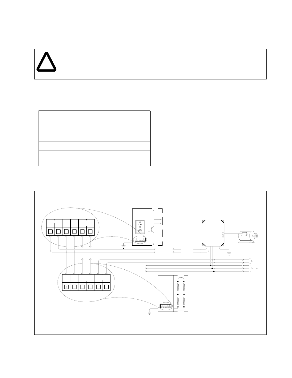
Figure 8 – Braking Transistor and Braking Resistor Unit Field Connections
AC
DRIVE
Ground
3 Line
Ground
Motor And Drive
M3575T with M3575R Braking Module Field Connections
Notes
The minimum load requirement must be followed.
DC BUS
115VAC
ALARM
TEMP
115 VAC
Alarm contacts open upon a fault and are rated at 0.5 amps (115 VAC).
1.
2.
3.
RES
DC+
DC-
Note 4
See
Note 2
See
To Braking
Module
Ground
M3575T
-DC Bus
+DC Bus
See Note 3
M3575R
1
2
3
4
5
6
+
-
RES RES
RES RES
115VAC
(
OPTIONAL
)
FAN
2
3
4
5
6
Refer to drive instruction manual for drive connections.
FAULT
ALARM
1
Alarm contacts open upon a fault and are rated at 2.0 amps (125 VDC or 125 VAC).
4.