Description, Figure 2 expander interface adaptor schematic, Table 1 odu connector pin assignments – Rockwell Automation T8312 Trusted Expander Interface Adaptor Unit User Manual
Page 7: Trusted, Expander interface adaptor t8312
Trusted
TM
Expander Interface Adaptor T8312
Issue 10 Jun 08
PD-T8312
7
1. Description
The Trusted
TM
Expander Interface Adaptor Unit T8312 comprises four, or seven 12-pin ODU
connectors (dependent on type of unit), a printed circuit board (pcb), a 96-way C type connector which
plugs into a double 96-way connector assembly designed to be connected to the Trusted
TM
Expander
Interface modules resident in the Controller Chassis. The Unit is contained within a metal enclosure
and is designed to be clipped onto the Controller Chassis rear connectors. A release button is
provided to enable the Unit to be disconnected.
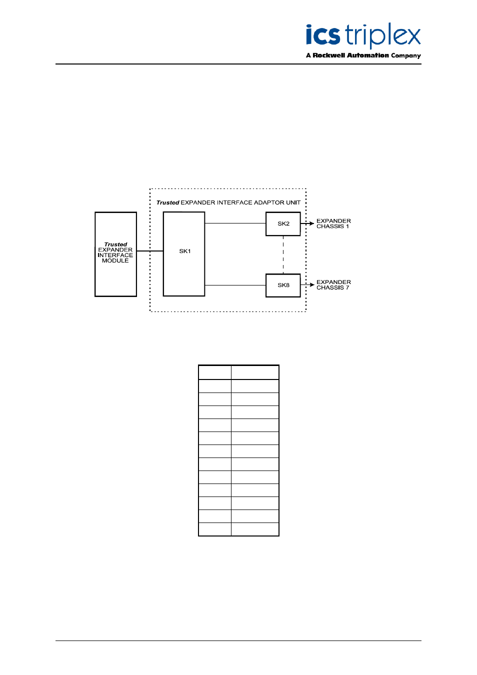
The illustration below shows the configuration of the Unit.
Figure 2 Expander Interface Adaptor Schematic
The ODU connectors are mounted on the rear of the Unit and are numbered to identify the Expander
Chassis which may be connected. The pin assignments for the ODU connectors are as follows:
Pin
Service
1
TXA+
2
TXA-
3
RXA+
4
RXA-
5
TXB+
6
TXB-
7
RXB+
8
RXB-
9
TXC+
10
TXC-
11
RXC+
12
RXC-
Table 1 ODU Connector Pin Assignments
The cable which must be used with the Unit is the 250MHz Communications Cable – TC-301-01.