Rack 1: do, Rack 2: state, Table 4 oem parameters – Rockwell Automation T8451 Trusted TMR 24V dc Digital Output Module - 40 Channel User Manual
Page 19: Table 5 rack 1: do descriptions, Table 6 rack 2: state descriptions, Trusted, Module t8451
Trusted
TM
Module T8451
Issue 12 Apr 10
PD-T8451
19
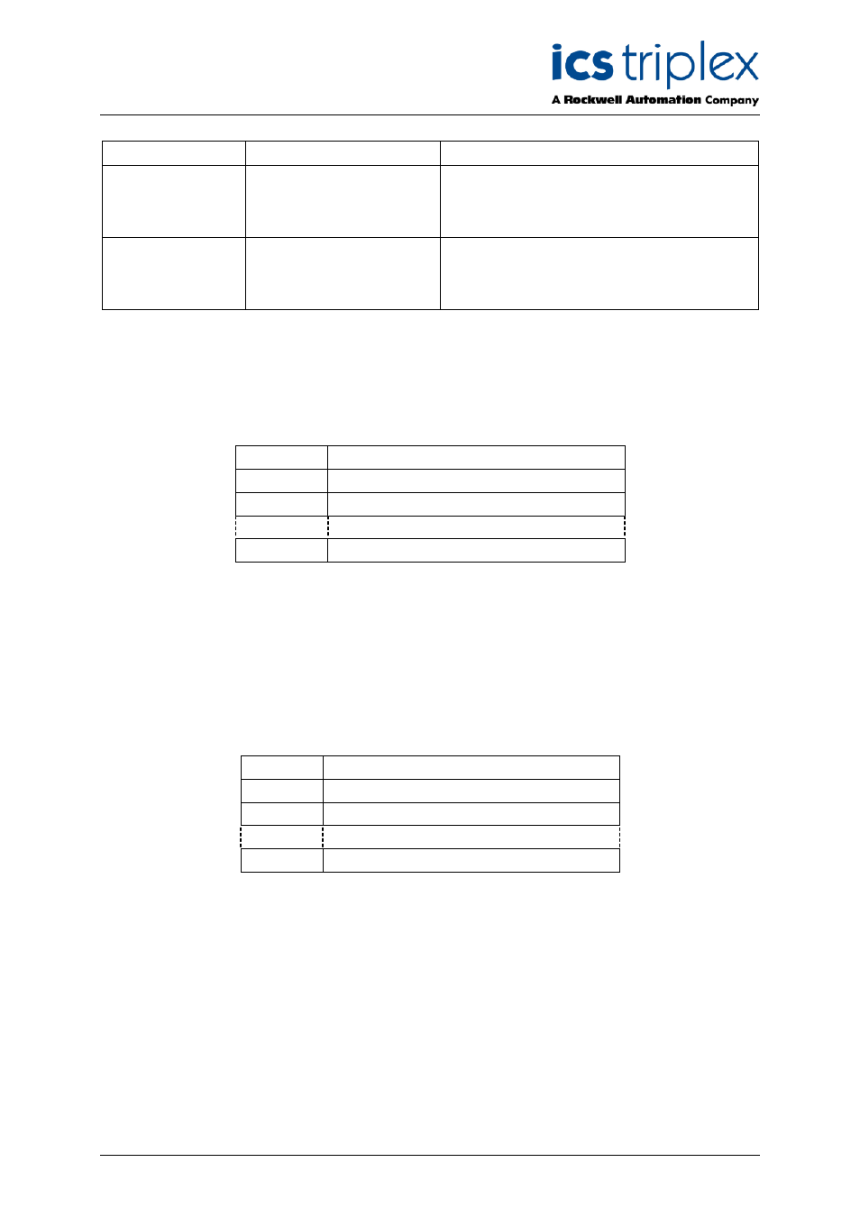
OEM Parameter
Description
Notes
TICS_CHASSIS
The number of the
Trusted
TM
Chassis where
the primary I/O module is
installed
The Trusted
TM
Controller Chassis is 1, and
Trusted
TM
Expander Chassis are 2 to 15
TICS_SLOT
The slot number in the
chassis where the primary
I/O module is installed
The I/O module slots in the Trusted
TM
Controller chassis are numbered from 1 to 8.
The I/O Module slots in the Trusted
TM
Expander Chassis are numbered from 1 to 12
Table 4 OEM Parameters
3.2.1. Rack 1: DO
This board provides the connection to the logical output control signal for each of the field outputs.
Channel
Description
1
Field output channel 1 logical state
2
Field output channel 2 logical state
40
Field output channel 40 logical state
Table 5 Rack 1: DO descriptions
The user application should set the output control signal to true (logic ‘1’) to turn ON or energise an
output, and false (logic ‘0’) to turn OFF or de-energise an output.
3.2.2. Rack 2: STATE
This board provides the majority voted numerical output state. This indicates the operational status of
the output channel and associated field connection.
Channel
Description
1
Field output channel 1 state
2
Field output channel 2 state
40
Field output channel 40 state
Table 6 Rack 2: STATE descriptions