Sequence of events characteristics, Output switch structure, Figure 3 output switch structure – Rockwell Automation T8451 Trusted TMR 24V dc Digital Output Module - 40 Channel User Manual
Page 12: Trusted, Module t8451
Trusted
TM
Module T8451
Issue 12 Apr 10
PD-T8451
12
The power supplies for both the HIU and FIU boards are redundant, fully instrumented and testable.
Together these assemblies form a Power Integrity Sub System.
1.8. Sequence of Events Characteristics
The module automatically measures the field voltage and current to determine the state of each output
channel. An event occurs when the output transitions from one state to another. When a channel
changes state, the on-board timer value is recorded. When the TMR Processor next reads data from
the output module, the channel state and real-time clock value are retrieved. The TMR Processor
uses this data to log the state change into the system Sequence of Events (SOE) log. The user may
configure each output to be included in the system SOE log. Full details of SOE are contained in PD-
8013 Trusted
TM
SOE and Process Historian.
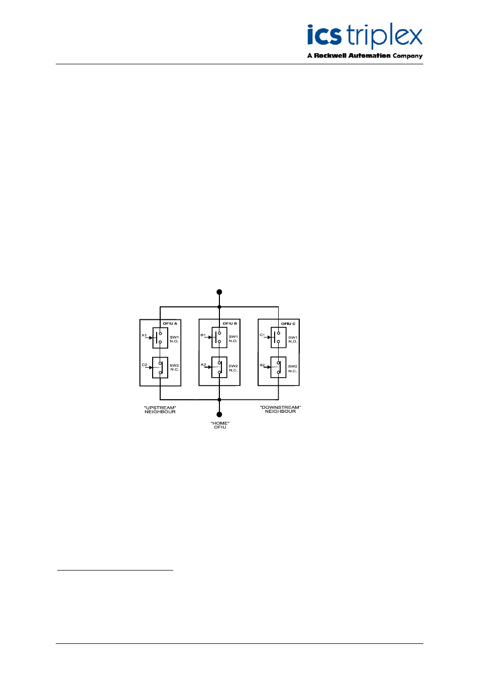
1.9. Output Switch Structure
The Digital Output Module provides a TMR switch topology where the load is driven by a total of three
fully monitored, fail-safe (6 element) switch channels, one physically resident on each OFIU in the
module. Any single switch or entire slice failure is designed to leave two of the three fail-safe switch
channels operational to power the load.
Figure 3 Output Switch Structure
The upper switches as shown in Figure 3 are denoted as N.O. (Normally Open), and are controlled by
the FIU on which they are physically resident.
The lower switches are depicted as N.C. (Normally
Closed), and are controlled by the “upstream” neighbouring FIU.
Note:
In this context, N.O. is defined as being in the off state in the absence of control signal power,
and similarly, N.C. is the on state in the absence of control signal power. These switches are
constructed from enhancement mode MOSFETs and are both guaranteed to be off in the
absence of module power to create gate voltage signals to bias them on
(unlike
electromechanical relays for example).
1
Their “home” FIU.
2
The home FIU, supplies an independent control signal for the “downstream” FIU FSS.
3
For an un-faulted transistor.