Rockwell Automation T3150A ICS Regent Communications Module User Manual
Page 12
Communications Modules (T3150A)
1 2
Industrial Control Services
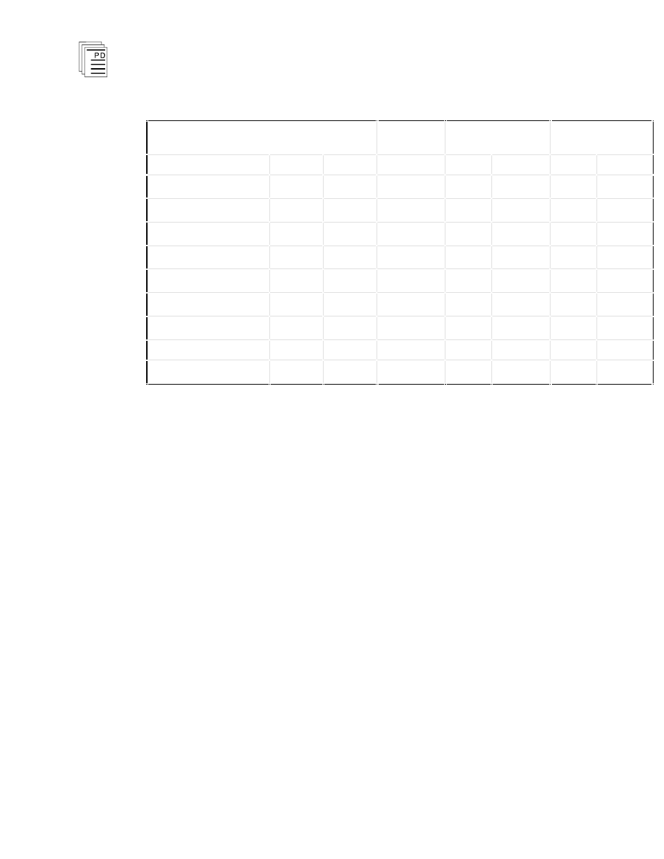
Table 2. Communication Module Jumper Settings.
Note: n indicates jumper installed
Point-to-
Point
Multidrop (Regent
R2 or Modbus)
Guarded Peer-
Link
Description
Port 1
Port 2
End
Middle
End
Middle
TX pair terminator
E101
E201
n
RX pair terminator
E102
E202
n
n
n
TX (-) pull-up
E111
E211
n
RX (-) pull-up
E112
E212
n
n
n
TX (+) pull-down
E121
E221
n
RX (+) pull-down
E122
E222
n
n
n
Transmit control
E131
E231
n
n
n
n
Transmit control
E132
E232
Transmit control
E133
E233
n
n
n
n
Termination, Pull-up and Pull-down Resistor Jumpers
When the module is used for RS422 or RS485
communications, the jumper positions for the internal
termination, pull-up and pull-down resistors must be
considered. Each termination resistor connects an internal
120 Ohm resistor across a specific differential pair and the
pull-up and pull-down resistors connect a 1K Ohm resistor
between each signal line and +5V or Comm. These resistors
should be connected only at the end nodes of the multidrop
communication network. Nodes in the middle should not have
these jumpers connected.
Figure 7 identifies the signal lines, resistors and jumpers
associated with each port. Only the transmit (TX+ and TX-)
and receive (RX+ and RX-) signal pairs are shown. Other
jumpers and resistors for signal pairs CTS, RTS, DTR and
DSR are also located on the module but they are not used by
serial communications for the Regent and their jumper
positions are not important.
If desired, you can install the termination, pull-up and pull-
down resisters external to the communications module at the
ends of the multidrop network. In this case position the
jumpers in each communications module for a “middle”
Note: