Rockwell Automation 20D PowerFlex 700H/700S AC Drives Frames 13 and 14 Main Fan Capacitor Rplcmnt. Kit User Manual
Page 17
Rockwell Automation Publication PFLEX-IN027A-EN-P - July 2011
17
PowerFlex 700H and 700S AC Drives Frames 13 and 14 Main Fan Capacitor Replacement Kit
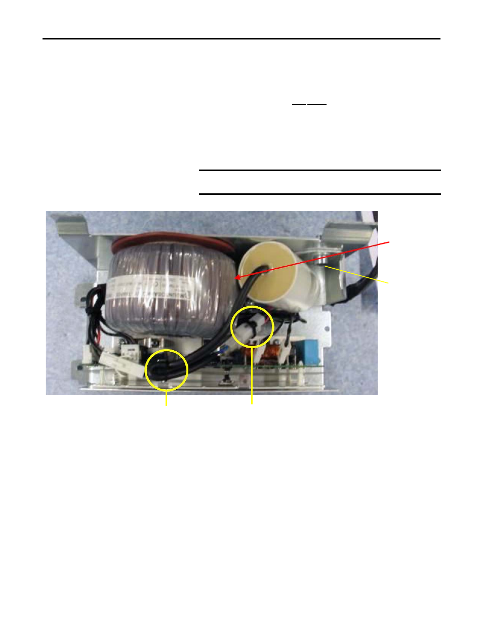
14. Secure the fan capacitor bracket (and fan capacitor) to the fan inverter
assembly using the M8 x 12 mm hexagonal socket screw and spring washer
provided as shown below. Secure the capacitor in a position that allows the
maximum amount of clearance possible between the transformer and
capacitor, ensuring that they DO NOT touch. Tightening torque is
20 N
•
m (178 lb
•
in).
15. Connect the new fan capacitor wires to the connectors marked “Brown”
and “Blue.”
16. Secure the fan capacitor wires to the fan wire bundle using cable ties.
17. Complete the remaining installation in the reverse order of removal as
detailed in the previous steps for the Inverter Unit.
IMPORTANT
Verify that no wire shields are touching the sheet metal on the
fan inverter assembly.
IMPORTANT:
Verify that the fan
capacitor does not
touch the fan
transformer.
Secure fan bracket
(and capacitor) to
fan inverter
assembly using
hexagonal socket
screw and washer in
orientation shown
at left
Secure fan capacitor
wires to wire bundle
using cable ties
Connect fan capacitor
wires to “Brown” and
“Blue” connectors