Rack 1: di, Rack 2: state, Table 5 oem parameters – Rockwell Automation T8423 Trusted TMR 35 - 120 Vdc Digital Input Module User Manual
Page 20: Table 6 rack 1: di descriptions, Table 7 rack 2: state descriptions, Trusted, Module t8423
Trusted
TM
Module T8423
Issue 15 Apr 10
PD-T8423
20
OEM Parameter
Description
Notes
TICS_CHASSIS
The number of the Trusted
TM
Chassis where the primary
I/O module is installed
The Trusted
TM
Controller Chassis is 1, and
Trusted
TM
Expander Chassis are 2 to 15
TICS_SLOT
The slot number in the
chassis where the primary
I/O module is installed
The I/O module slots in the Trusted
TM
Controller chassis are numbered from 1 to 8.
The I/O Module slots in the Trusted
TM
Expander Chassis are numbered from 1 to 12
Table 5 OEM Parameters
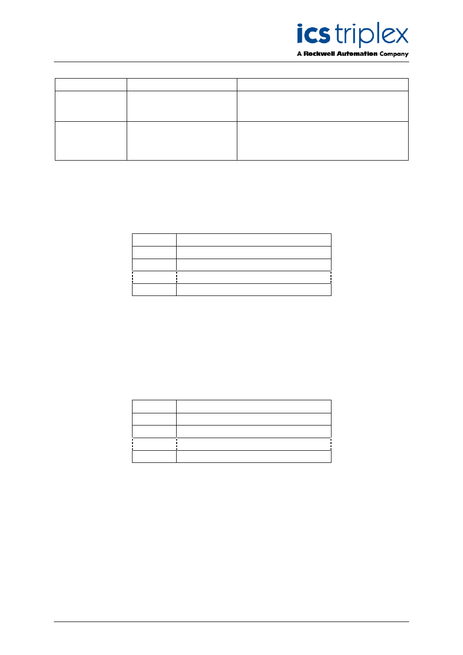
3.2.1. Rack 1: DI
This board provides the logical input state for each of the field inputs.
Channel
Description
1
Field input channel 1 logical state
2
Field input channel 2 logical state
40
Field input channel 40 logical state
Table 6 Rack 1: DI descriptions
The input state is reported as true (logic ‘1’) for a closed contact input, and false (logic ‘0’) for an open
contact input. The logic state is the majority voted value.
3.2.2. Rack 2: STATE
This board provides the majority voted numerical input state. This input channel state indicates the
threshold band within which the input voltage lies.
Channel
Description
1
Field input channel 1 state
2
Field input channel 2 state
40
Field input channel 40 state
Table 7 Rack 2: STATE descriptions