Application, Module configuration, T8423 complex equipment definition – Rockwell Automation T8423 Trusted TMR 35 - 120 Vdc Digital Input Module User Manual
Page 19: Table 4 complex equipment definition, Trusted, Module t8423
Trusted
TM
Module T8423
Issue 15 Apr 10
PD-T8423
19
3. Application
3.1. Module Configuration
There is no configuration required to the physical input module. All configurable characteristics of the
module are performed using tools on the EWS and become part of the application or system.ini file
that is loaded into the TMR Processor. The TMR Processor automatically configures the input module
after applications are downloaded and during Active/Standby changeover.
The IEC1131 TOOLSET provides the main interface to configure the input module. Details of the
configuration tools and configuration sequence are provided in PD-8082 Trusted
TM
Toolset suite.
There are three procedures necessary to configure the input module. These are:
1. Define the necessary I/O variables for the field input data and module status data using the
Dictionary Editor of the IEC1131 TOOLSET.
2. Create an I/O module definition in the I/O Connection Editor for each I/O module. The I/O
module definition defines physical information, e.g. Chassis and Slot location, and allows
variables to be connected to the I/O channels of the module.
3. Using the Trusted
TM
System Configuration Manager, define custom LED indicator modes,
per-channel threshold levels and noise filtering, and other module settings.
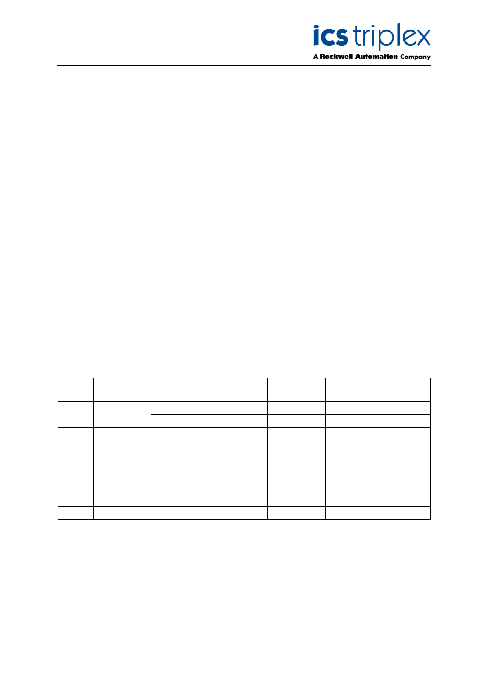
3.2. T8423 Complex Equipment Definition
The T8423 I/O Complex Equipment Definition includes 8 I/O boards, referenced numerically by Rack
number:
Rack
I/O Board
Description
Data Type
Direction
No. of
Channels
OEM Parameters
-
-
-
1
DI
Field Input Status
Boolean
In
40
2
STATE
Field Input State
Integer
In
40
3
AI
Input voltage
Integer
In
40
4
SPARE
Not used
Integer
-
16
5
LINE_FLT
Line Fault Status
Boolean
In
40
6
DISCREP
Channel Discrepancy
Integer
In
3
7
HKEEPING
Housekeeping Registers
Integer
In
51
8
INFO
I/O Module Information
Integer
In
11
Table 4 Complex Equipment Definition
There are two OEM parameters included in the first rack (DI Board). These OEM parameters define
the primary module position; declaring the module’s chassis and slot location. There is no need to
define the secondary module position within the IEC1131 TOOLSET. Where systems may be required
to start-up with a module in the secondary position as the active module, e.g. primary module is not
installed when application is started, the secondary module’s position should be declared in the module
definition of the System Configuration Manager.