Rockwell Automation 20G PowerFlex 750-Series Replacement Board Kits User Manual
Page 4
Rockwell Automation Publication RA-IN028C-EN-P - January 2013
4
PowerFlex 750-Series Board Replacement Kits
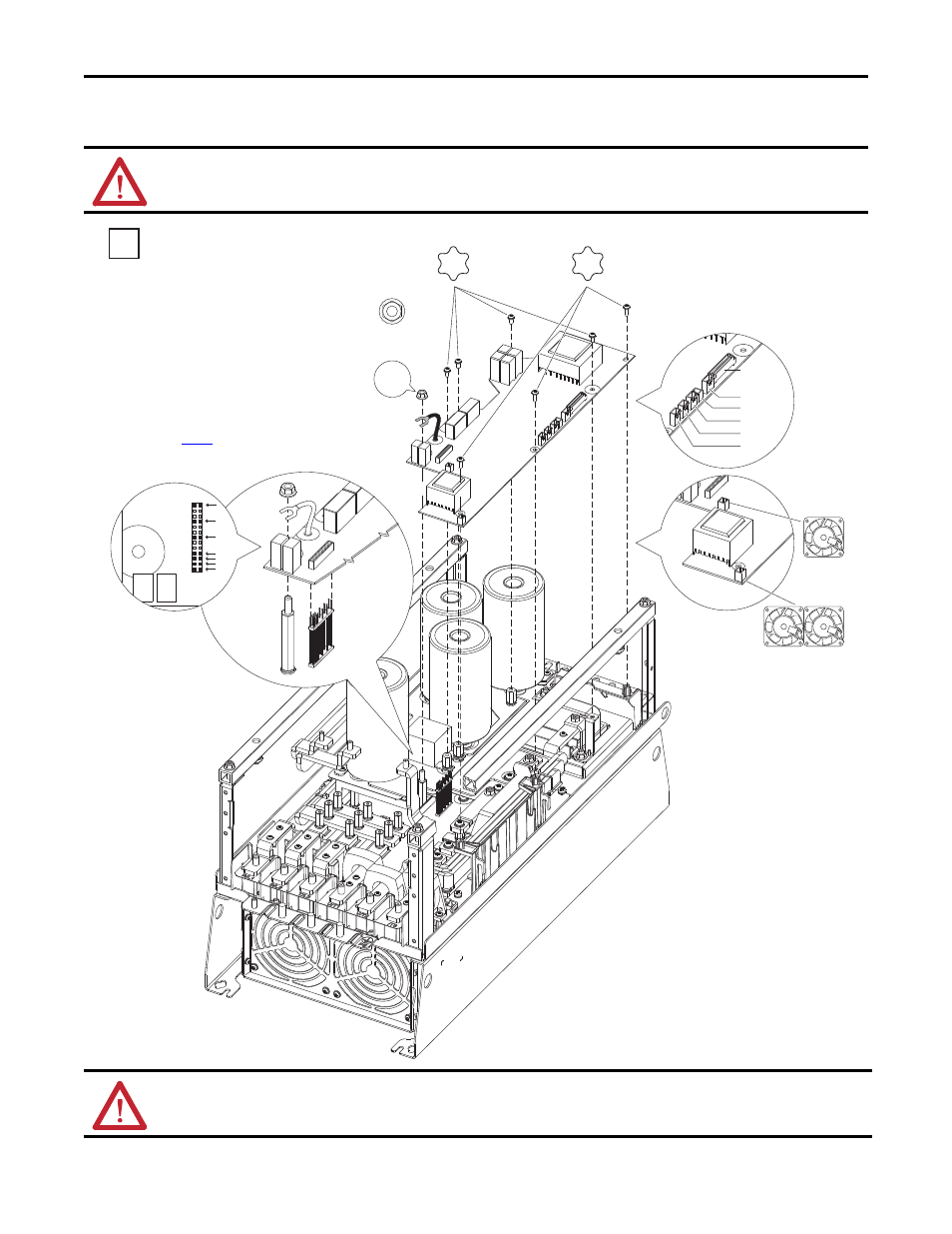
400/480V Frame 6 Drives – Power Interface Board
400V: SK-R9-PINT1-CF6A, -CF6B, -CF6C, -CF6D / 480V: SK-R9PINT1-DF6A,-DF6B, -DF6C, -DF6D
ATTENTION: Replacing the Power Interface Board will result in the loss of drive data including elapsed power
consumption, elapsed run times, and preventive maintenance data.
2
2.6 N•m (23 lb•in)
T20
M6 x 1.0
2.6 N•m (23 lb•in)
1.3 N•m (12 lb•in)
T20
U/T1
V/T2
W/T3
NTC
Precharge
MCB
PE-B
IMPORTANT: Note the position of the
PE-B jumper wire before disassembly.
Use the same position when installing
the replacement board.
Positions are identified in Step 1 on
ATTENTION: Hazard of equipment damage exists if any board connector is not in full contact with its corresponding
socket when power is applied. When installing the replacement board, be sure the pin connector is aligned, all plugs are
fully seated, the PE-B jumper wire is properly terminated, and all fasteners are installed and torqued as indicated.