Rockwell Automation 2090-MPPC-X163 Size 36 Connector Kit for MP-B9xx Motor Power User Manual
Page 2
Publication MP-IN011B-EN-P - April 2007
Supersedes publication MP-IN011A-EN-P December 2006
Copyright © 2007 Rockwell Automation, Inc. All rights reserved. Printed in the U.S.A.
2. Secure a contact pin on each wire lead.
a. Strip the wire lead to 16.5 mm (0.65 in.).
b. Fully insert the lead into the contact pin to the full depth of the pin.
Less than 2.5 mm (0.1 in.) of wire should be visible between the contact pin and
the wire insulation.
c. Solder or crimp the lead to the contact pin.
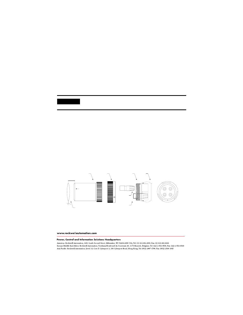
3. Insert each connector pin in the appropriate location of the connector housing.
a. Verify the pin location before beginning to insert the pin.
b. Insert each contact pin fully.
The groove in the contact should fully engage the rib in the connector hole. The
contact should extend 8.9 mm (0.350 in.) from the rear of the connector housing.
4. Repeat steps 2 and 3 for each of the four power leads.
5. Fully seat the O-ring over the smooth end of the connector housing.
6. Thread the connector housing into the backshell, and hand-tighten.
Allen-Bradley and Rockwell Automation are trademarks of Rockwell Automation, Inc.
IMPORTANT
If soldering the wire-to-pin connection, provide an adequate cooling period
before inserting the pin.
A
B
C
D
Backshell Lock
Ring
360° power wire
shielding required.
Four (4) pins extend
8.9 mm (0.35 in.) from
back of housing.
Fully seat o-ring
on connector
housing.
A = U Power B = V Power
C = W Power D = Ground
Connector
Housing
O-ring
Rear View of Connector
with Pin Locations
Contact
Pin
Backshell
threaded
1 1/2 NPT.