Block diagram, Electrical specification, Sds-8448 trusted – Rockwell Automation T8448 Trusted TMR Zone Interface Module User Manual
Page 2: Industrial control system trusted, Tmr zone interface module-t8448, Ics triplex, Mechanical specification, Environmental, Ofiu hiu fpdu fpiu, Oftu
SDS-8448
Trusted
TM
Industrial Control System
Trusted
TM
TMR Zone Interface Module-T8448
ICS Triplex
Technical data sheets are intended for
information and guidance. The Company
has a policy of continual product
development and improvement.
Specifications are subject to change
without notice. For latest information, visit
our Website:-
www.icstriplex.com
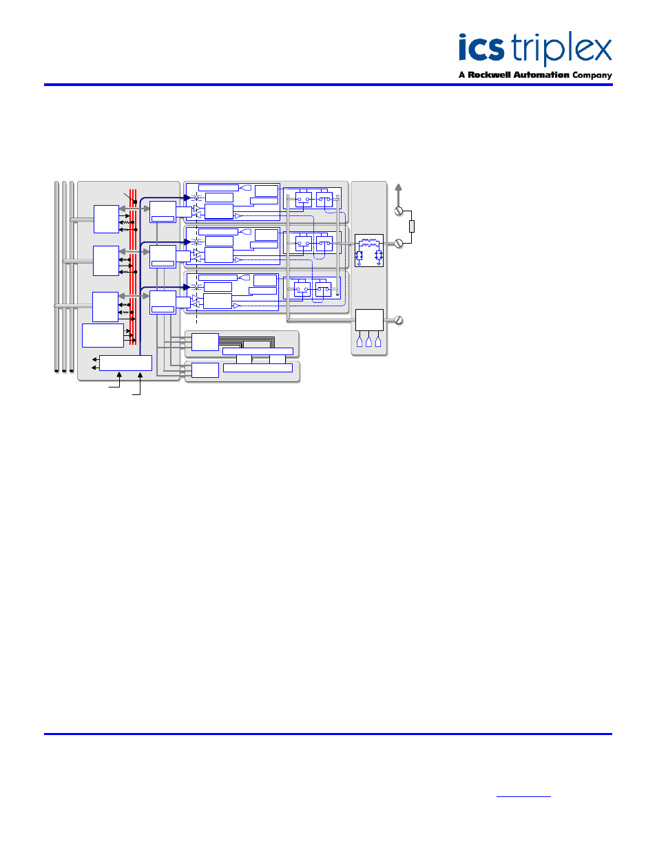
BLOCK DIAGRAM
ELECTRICAL SPECIFICATION
Number of Channels
40 input or output
No. of Power Groups
5, each of 8 outputs
Field Common Isolation
Sustained Working
±250V dc
Maximum Withstanding
±2.5kV dc
Output Voltage Field Supply
Measurement Range
0 to 36V dc
Maximum Withstanding
-1 to 60V dc
Output Current Rating
Continuous
2A
Output Off Resistance (effective
leakage)
33k>
Power Consumption (1A per channel) 24W
Output Turn On/Off Delay
0.5ms
Self-Test Interval
2 minutes
Output Short Circuit Protection
Automatic
Fusing
Not required
Intrinsic Safety
External barrier
Circuit Type
Fault tolerant, fully triplicated with
optional line monitoring
MECHANICAL
SPECIFICATION
Dimensions (HxWxD):
241mm x 30mm x 300mm
(9.5ins x 1.2ins x 11.8ins)
Weight:
1.13kg
(2.5lbs)
ENVIRONMENTAL
Operating Temperature:
-5
°C to 60°C
(23
°F to 140°F)
Operating Humidity:
5 to 95%, non-
condensing
Vibration:
10 to 57Hz
±0.075mm
57 to 150Hz 1.0g
Shock:
15g, ½ sine wave, 11ms
EMI (IEC 801):
ESD
Air discharge to 15kV
Contact discharge to 8kV
Radiated Fields
10V/m, 27MHz to
500MHz
Transients and Bursts
2kV, 2.5kHz for
t=60 seconds
Slice Power
Supply
Housekeeping
Failsafe Bias Control
A
Back Plane
Power Bus
1
Front Panel
T
M
R
In
te
rm
o
d
u
le
B
u
s
Opto Isolation Boundary
Serial Display Latches
Voted Status Display LEDs
Internal Voting Bus
Housekeeping
Module Temp
Supply Diag
DSP reference
Health
Indicators
Back Plane Power Bus 1
Back Plane Power Bus 2
Slice A
OFIU
HIU
FPDU
FPIU
Field Logic
Control
Redundant Supply
N.C.
N.O.
Diagnostic
Monitor
Bus
Interface
Bus
Interface
Slice Power
Supply
Housekeeping
Failsafe Bias Control
B
Field Logic
Control
N.C.
N.O.
Diagnostic
Monitor
Slice Power
Supply
Housekeeping
Failsafe Bias Control
C
Field Logic
Control
N.C.
N.O.
Diagnostic
Monitor
Bus
Interface
Front Panel
Voting Logic
Slice
Control
B
Time Stamp
Slice
Control
B
Time Stamp
Slice
Control
A
Time Stamp
OFTU
+V
Slice B
Slice C
A
B
C
Group
Fail-Safe
Switch
-
V
Field Interface
Protection Circuit