Rockwell Automation 20D PowerFlex 700H and 700S AC Drives Frame 9 Main Fan Capacitor Replacement Kit User Manual
Page 5
Rockwell Automation Publication PFLEX-IN024B-EN-P - September 2011
5
PowerFlex 700H and 700S AC Drives Frame 9 Main Fan Capacitor Replacement Kit
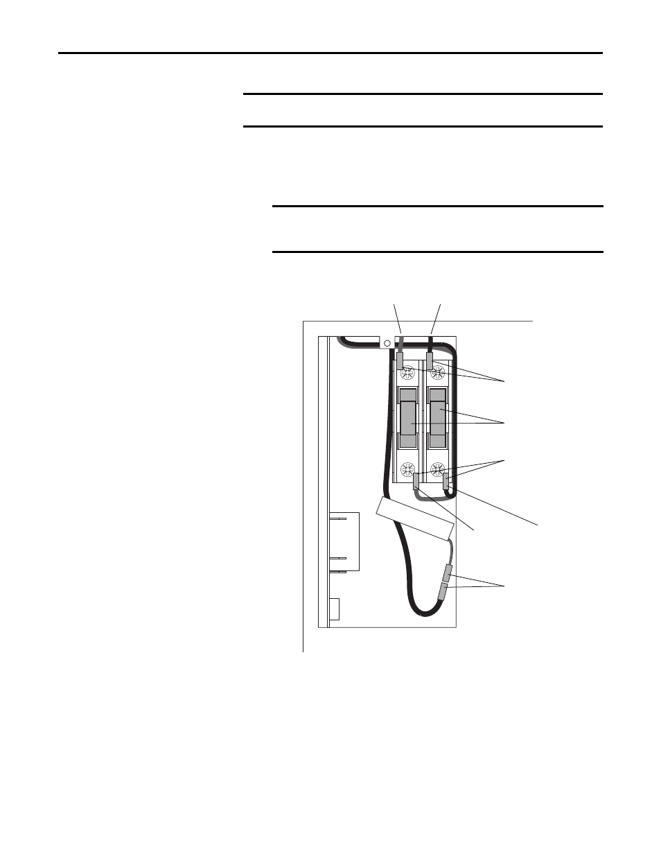
3. Remove the fuses from the fuse holder.
4. Disconnect the four fuse signal wires (black and red pairs) connected to
the top and bottom of the fuse holder.
5. Disconnect the stirring fan power wires.
6. Remove the two M5 x 10 mm POZIDRIV screws that secure the fan
capacitor, fuse holder and fan bracket to the drive frame, and lift the
bracket out of the drive. Note that the fan capacitor is still connected to
the drive circuitry. Discard the two M5 x 10 mm screws -- new hardware is
provided in the kit.
7. Disconnect the capacitor wires from the connectors labelled “Blue” and
“Brown”.
IMPORTANT
Mark all connections and wires before removing to avoid incorrect
wiring during reassembly.
IMPORTANT
Note that the red wires connect to the left side terminal on the
fuse holder and the black wires connect to the right side
terminal on the fuse holder.
Disconnect fuse signal
wires from fuse holder
Disconnect fuse signal
wires from fuse holder
Remove fuses
from fuse holder
Disconnect stirring
fan power wires
Red wire
Black wire
Red wire
Black wire