Digital inputs, Trusted, Thresholds – Rockwell Automation T80004 Application Note Field Loop Configuration User Manual
Page 16
Trusted
TM
AN-T80004 Field Loop Configuration
Issue 10 Jun 13
AN-T80004
16
Digital Inputs
Thresholds
Digital inputs are essentially analogue inputs which are interpreted as digital. The voltage on the input
circuit is measured and allocated to an input state using thresholds, similar to analogue inputs above.
For digital inputs, the state bands are essential, since they define the digital input ‘off/open’ and
‘on/closed’ as well as line fault status. The thresholds are similar to analogue inputs except that they
operate over a wider voltage range. There are five configurable states separated by pairs of thresholds
for rising and falling state change. There are no THRSHIN and THRSHOUT boards to change the
thresholds online.
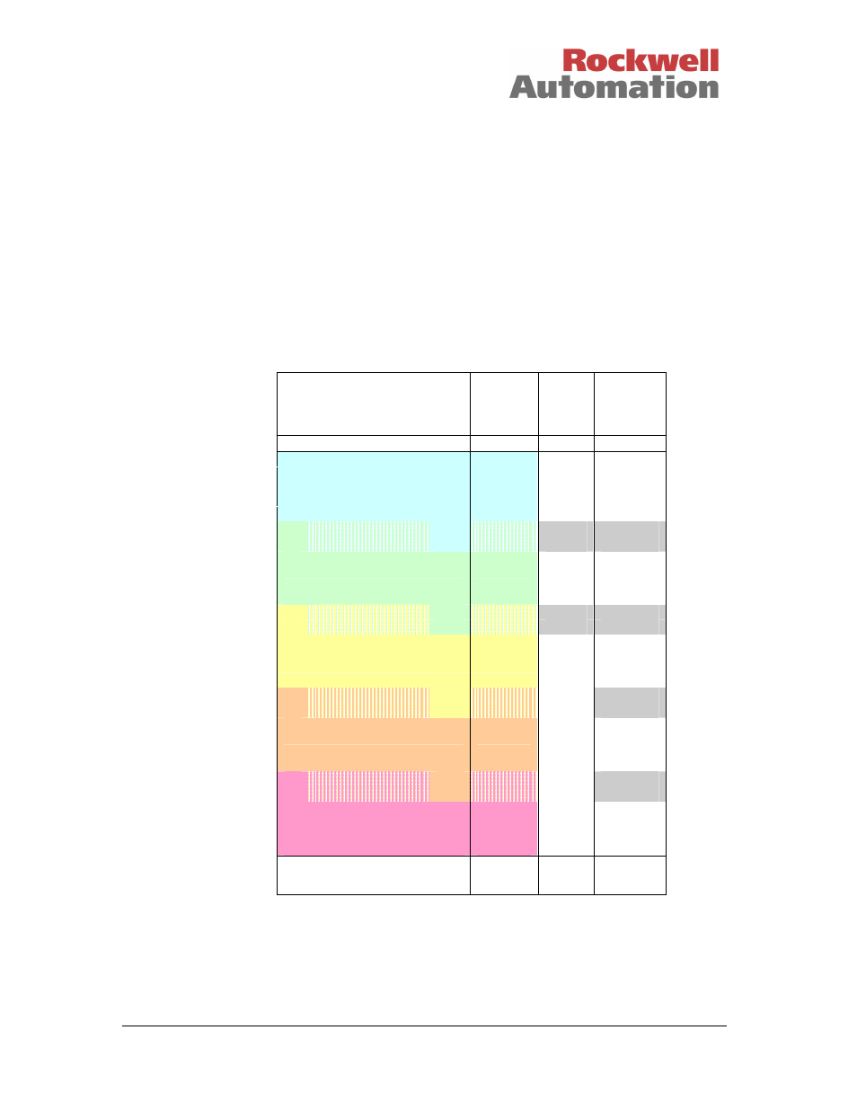
Typical
voltage
threshold
values
Input
Channel
State
DI
Status
Line
Fault
Status
Over-range
7
False
True
Tmax 36.00
False
True
Short Circuit (approx 24V)
5
T8 22.00
4 or 5
False /
False /
T7 21.00
True
True
Contact Closed (approx 16V)
4
True
False
T6 12.75
3 or 4
False /
False /
T5 12.25
True
True
Contact Indeterminate
3
False
True
T4 11.75
2 or 3
False /
T3 11.25
True
Contact Open (approx 8V)
2
False
False
T2 3.00
1 or 2
False /
T1 2.00
True
Open Circuit (approx 0V)
1
False
True
Tmin -8.00
Under-range
7
False
True
Thresholds are defined using a threshold template in the system configuration. Product description PD-
8082 describes how to edit threshold templates. The example above shows ‘Closed’ defined at
nominally 16 volts and ‘Open’ at nominally 8 volts, for a 24V digital input module. These are spaced
equally through the input voltage range, which allows broad voltage bands for each state.