Trusted, Configuration – Rockwell Automation T80004 Application Note Field Loop Configuration User Manual
Page 13
Trusted
TM
AN-T80004 Field Loop Configuration
Issue 10 Jun 13
AN-T80004
13
Configuration
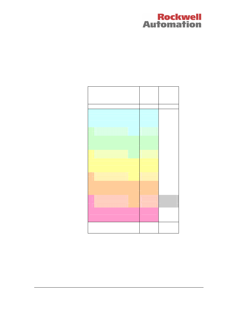
There are seven input voltage state thresholds detected by all of the analogue input modules,
numbered 0 to 6. States 0 and 6 are ‘out of range’ indications, outside of the normal operating range.
The remaining five are configurable using the System Configuration Manager. The voltage transition
between each state can be split into a rising transition and a falling transition. In the diagram below, the
input goes from state 4 to state 5 as it rises above 2.28V. It returns to state 4 as it falls below 2.24V.
There are four configurable pairs of state transitions, numbered T1 to T8 below. These are configured
using a threshold template as described in product description PD-8082.
Typical
voltage
threshold
values
Input
Channel
State
Line
Fault
Status
Over-range
6
True
Tmax 6.0
High-High
5
T8
2.28
4 or 5
T7
2.24
High
4
T6
1.82
3 or 4
T5
1.79
Normal
3
False
T4
1.52
2 or 3
T3
1.47
Low
2
T2
1.12
1 or 2
False /
True
T1
1.11
Low-Low
1
True
Tmin
-0.5V
Under-range
0
True
The input states can be used to define alarm trips, detector conditions, near-overrange signals, valve
positions on analogue position sensors etc. There is room to define states for input conditions like gas
detector dirty optics as well as alarm thresholds. Note that state 1 indicates a line fault.
The system configuration for I/O modules can only be loaded when the system is shut down and
restarted. This includes threshold changes. However, there is an online method for entering a new set
of thresholds using the THRSHIN and THRSHOUT boards which is described below. Alternatively the
analogue reading may be converted in the application using comparative logic.