Installing the kinetix 6000 drive modules, Determining mounting order – Rockwell Automation 2094 Kinetix 6000 Axis Module and Shunt Module Install User Manual
Page 4
Publication 2094-IN004D-EN-P — September 2006
4
Kinetix 6000 Axis Module and Shunt Module
Installing the Kinetix 6000
Drive Modules
These procedures assume you have mounted your power rail and
integrated axis module (IAM). Each power rail accommodates one
IAM and up to seven additional modules (either axis or shunt). You
must mount a slot filler in any slot not occupied by another module.
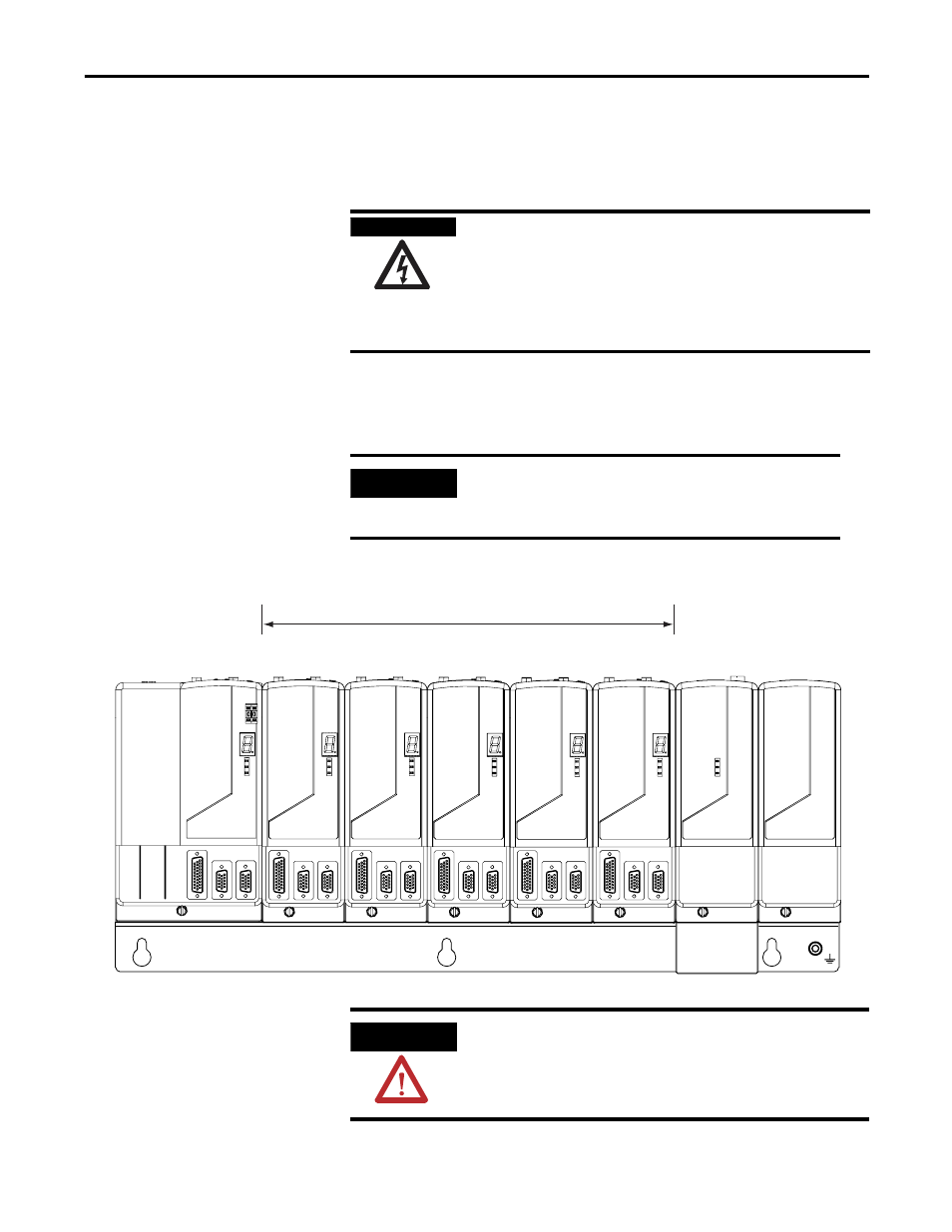
Determining Mounting Order
Module Mounting Order
SHOCK HAZARD
To avoid personal injury due to electrical shock, place a slot
filler module (catalog number 2094-PRF) in any empty slot on
the power rail.
Any power rail connector without a module installed will
disable the Kinetix 6000 system, however control power will
still be present.
IMPORTANT
Mount axis modules according to ampere rating (highest to
lowest) from left to right starting with the highest ampere
rating.
Highest Power Utilization or Amp Rating
Lowest Power Utilization or Amp Rating
Integrated Axis Module
2094-AC09-M02
Axis Module
2094-AM02
Axis Module
2094-AM02
Axis Module
2094-AM02
Axis Module
2094-AM01
Axis Module
2094-AM01
Shunt Module
2094-BSP2
Slot Filler Module
2094-PRF
ATTENTION
To avoid damage to the power rail during installation, do not
remove the protective boots until the module for each slot is
ready for mounting.