Before you begin – Rockwell Automation 2094 Kinetix 6000 Axis Module and Shunt Module Install User Manual
Page 3
Publication 2094-IN004D-EN-P — September 2006
Kinetix 6000 Axis Module and Shunt Module
3
Before You Begin
Remove all packing material, wedges, and braces from within and
around the components. After unpacking, check the item name-plate
catalog number against the purchase order.
Drive Component Box Contents
Motor and auxiliary feedback and I/O connectors are not provided.
Refer to the Kinetix Motion Control Selection Guide, publication
GMC-SG001, for connector kit catalog numbers.
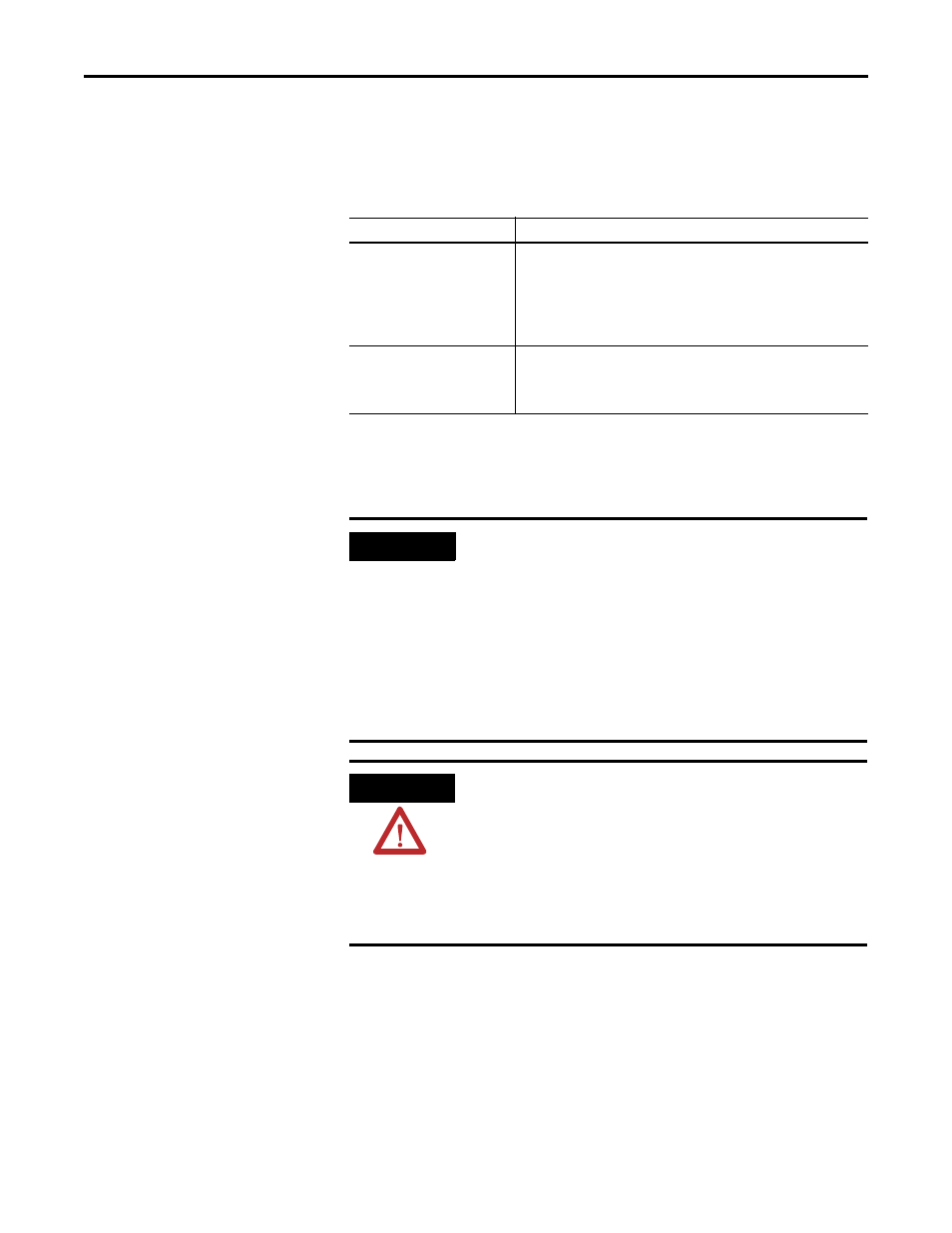
Drive Component
Ships With
Axis Module (AM)
• Wiring plugs for motor power (MP) and motor/resistive brake
power (BC).
• Wiring plug header for safe-off (SO) connector and motion
allowed jumper.
• Installation Instructions, publication 2094-IN004.
Shunt Module (SM)
• Wiring plug for an external shunt resistor (RC).
• Wiring plug for the thermal switch (TS).
• Installation Instructions, publication 2094-IN004.
ATTENTION
This drive contains ESD (Electrostatic Discharge) sensitive parts
and assemblies. You are required to follow static control
precautions when you install, test, service, or repair this
assembly. If you do not follow ESD control procedures,
components can be damaged. If you are not familiar with static
control procedures, refer to Allen-Bradley publication
8000-4.5.2, Guarding Against Electrostatic Damage or any other
applicable ESD Protection Handbook.
IMPORTANT
The integrated axis module (IAM) must be positioned in the
leftmost slot of the power rail. Position your axis modules (AM),
shunt module (SM), and slot filler modules (PRF) to the right of
the IAM.
The SM must be installed to the right of the last AM. Only slot
filler modules may be installed to the right of the SM.
Do not mount the SM on power rails with a follower IAM.
Common-bus follower IAMs will disable the internal, rail
mounted, and external shunt modules.