Wiring, Connect wiring to the terminal base as shown below – Rockwell Automation 1797-IRT8 FLEX Ex Thermocouple/RTD Module User Manual
Page 8
8 FLEX Ex Thermocouple/RTD Input Module
Publication
1797-5.4 - June 2010
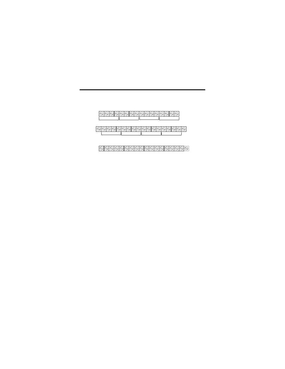
Wire to a 1797-TB3 or 1797-TB3S Terminal Base Unit
Connect wiring to the terminal base as shown below.
Wiring
1. For RTD inputs:
a. connect the individual source current input wiring to (+) terminals for
each individual channel (0, 4, 8, and 12) on the 0 to 15 row (A) and
terminals 17, 21, 25, and 29 on the 16 to 33 row (B) as indicated in the
table below.
b. connect the associated signal return (-) to the corresponding (-)
terminals (3, 7, 11, and 15) on the 0 to 15 row (A), and terminals 20, 24,
28, and 32 on the 16 to 33 row (B).
2. For thermocouple inputs:
a. connect the individual high signal input wiring to (L) terminals for
each individual channel (2, 6, 10, and 14) on the 0 to 15 row (A) and
terminals 19, 23, 27, and 31 on the 16 to 33 row (B) as indicated in the
table below.
b. connect the associated low signal (-) to the corresponding (-)
terminals (3, 7, 11, and 15) on the 0 to 15 row (A), and terminals 20, 24,
28, and 32 on the 16 to 33 row (B).
c. connect cold junction compensation wiring to terminals 37, 38, and
39, and terminals 46, 47, and 48.
+
-
Ch 0
Ch 1
Ch 2
Ch
3
+V -V
+V -V
0
1
2
3
4
5
6
7
8
9
10
11
12
1
3
14
15
16
17
1
8
19
20
21
22
2
3
24
25
26
27
2
8
29
3
0
3
1
3
2
33
3
4
3
5
3
6
3
7
38
3
9
40
41
42
4
3
44
45
46
47
4
8
49
50
51
L
H
+
-
L
H
+
-
L
H
+
-
L
H
+
-
Ch 4
Ch 5
Ch 6
Ch 7
L
H
+
-
L
H
+
-
L
H
+
-
L
H
CJC
0+
0-
CJC
1+
1-
Ch
ass
i
s
GND
for
s
hield
Row A
Row B
Row C
Ch
ass
i
s
GND
for
s
hield
No connection
a
llowed to termin
a
l
s
3
6,
a
nd 49
41505