Preliminary steps, Removing the tachometer feedback board, Installing the tachometer feedback board – Rockwell Automation 2361 Tachometer Feedback Board Replacement User Manual
Page 3
Tachometer Feedback Board Replacement
3
Preliminary Steps
Before replacing the tachometer feedback board, shut off the
drive power, wait five minutes for the voltage to discharge, open
the drive door; and remove any Lexan™ shielding as necessary.
Removing the Tachometer
Feedback Board
1.
Using a voltmeter, test the voltage across the three phases,
then across the board terminals.
2.
Observe the wiring and tag wires as necessary.
3.
Disconnect the tachometer leads (terminals 1, 2, and 3).
4.
Disconnect the adapter board leads (terminals 5 and 6).
5.
Disconnect the wire to TE (terminal 4).
6.
Snap the board out.
Installing The Tachometer
Feedback Board
Information for grounding, wiring, and scaling a tachometer is
given in the installation section of publication 1395-5.40, Bulletin
1395 Digital DC Drive–User Manual.
!
ATTENTION: If there is any voltage present,
remove the source of the voltage and check for
voltages again before proceeding to the next step.
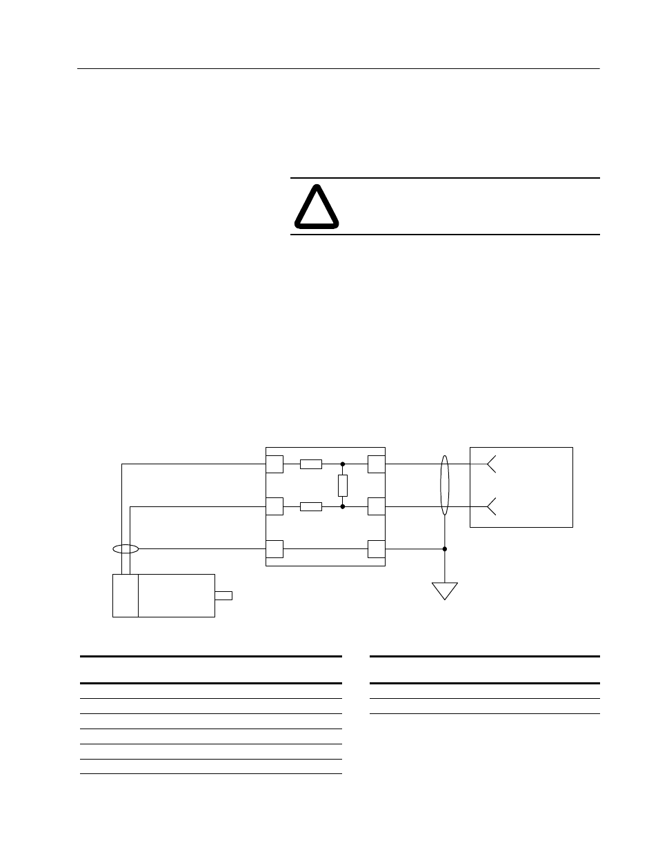
Tachometer Feedback Board
1
2
3
5
6
4
TE
DC Tachometer
+ -
Tach Velocity (+)
Tach Velocity (-)
Adapter Board
Kit Catalog
Number
Input Voltage
(From Tachometer)
Old 2361
Option Code
New 2361
Option Code
Tachometer
Feedback Board
Discrete
Adapter Board
Digital Reference
Adapter Board
2361-SPP01A
0-33V
14TFB
14T033
Terminal 5 (+)
TB3-24 (+)
TB3-33 (+)
2361-SPP02A
34-46V
14TFB
14T046
Terminal 6 (-)
TB3-23 (-)
TB3-34 (-)
2361-SPP03A
47-70V
14TFB
14T070
2361-SPP04A
71-125V
14TFB
14T125
2361-SPP05A
126-178V
14TFB
14T178
2361-SPP06A
179-250V
14TFB
14T250