Wiring requirements – Rockwell Automation 2198-CAPMOD-1300 Kinetix 5500 Capacitor Module Installation Instructions User Manual
Page 6
6 Kinetix 5500 Capacitor Module
Publication 2198-IN004A-EN-P - October 2012
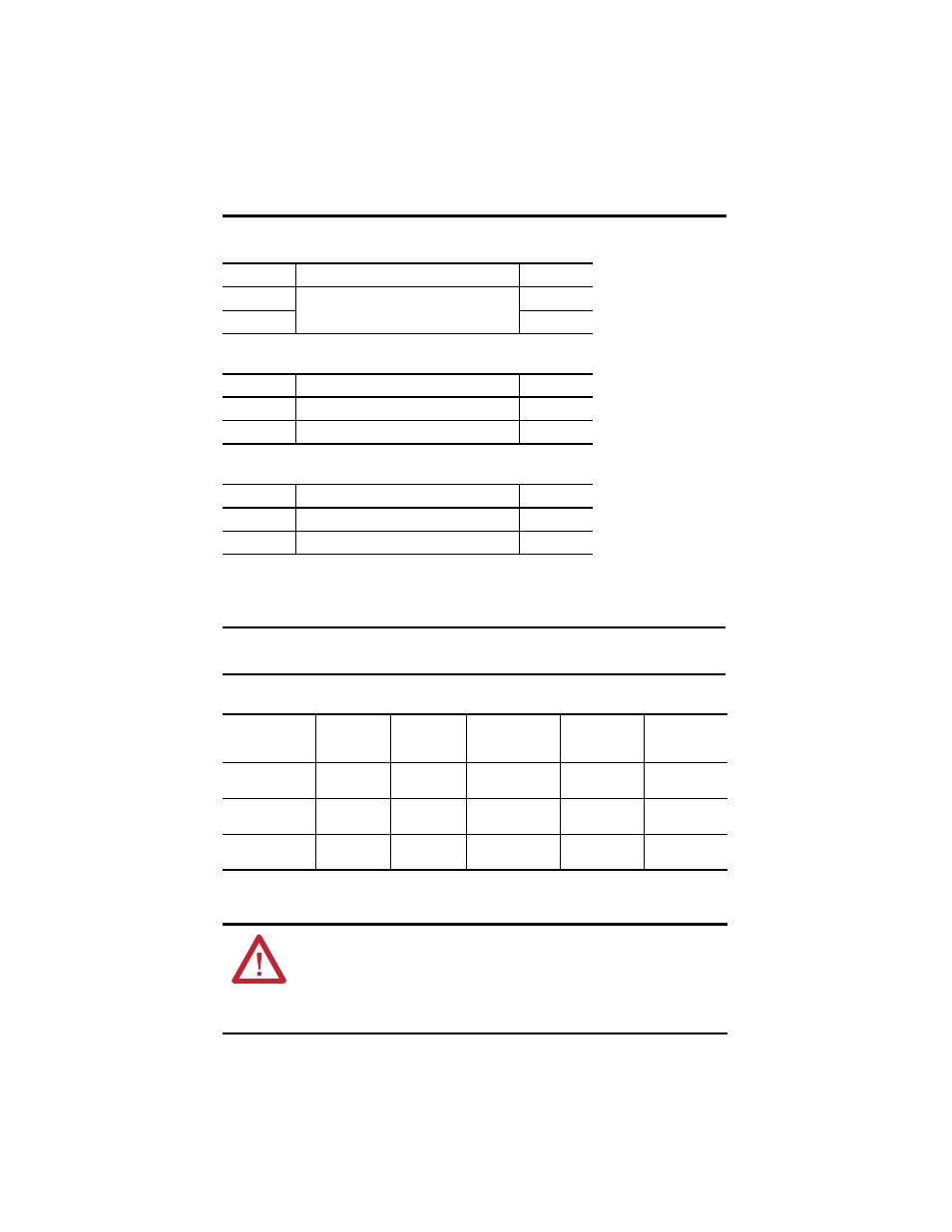
Table 2 - DC Bus (DC) Connector Pinout
Table 3 - Control Input Power (CP) Connector Pinout
Table 4 - Module Status (MS) Connector Pinout
Wiring Requirements
Table 5 - Capacitor Module Wiring Requirements
DC Pin
Description
Signal
1
DC bus connections
DC-
2
DC+
CP Pin
Description
Signal
1
24V power supply, customer-supplied
24V+
2
24V common
24V-
MS Pin
Description
Signal
1
Module status relay output +
RELAY+
2
Module status relay output -
RELAY-
IMPORTANT
The National Electrical Code and local electrical codes take precedence over the values and
methods provided.
Connector
Description
Pin
Signal
Recommended
Wire Size
mm
2
(AWG)
Strip Length
mm (in.)
Torque Value
N•m (lb•in)
Module Status
indicator
MS-1
MS-2
RELAY+
RELAY-
0.14…1.5
(28…16)
7.0 (0.28)
0.22…0.25
(1.9…2.2)
PELV/SELV
24V power
CP-1
CP-2
24V+
24V-
N/A
N/A
DC bus power
DC-1
DC-2
DC-
DC+
N/A
(1)
(1)
24V control power and DC bus connections are always made from drive-to-drive over the shared-bus connection system. These terminals do not
receive discrete wires.
N/A
ATTENTION: To avoid personal injury and/or equipment damage, observe the following:
• Make sure installation complies with specifications regarding wire types, conductor sizes,
branch circuit protection, and disconnect devices. The National Electrical Code (NEC) and local
codes outline provisions for safely installing electrical equipment.
• Use power connectors for connection purposes only. Do not use them to turn the unit on and off.
• Ground shielded power cables to prevent potentially high voltages on the shield.