Mount the capacitor module – Rockwell Automation 2198-CAPMOD-1300 Kinetix 5500 Capacitor Module Installation Instructions User Manual
Page 4
4 Kinetix 5500 Capacitor Module
Publication 2198-IN004A-EN-P - October 2012
Mount the Capacitor Module
Clearance requirements for the Kinetix 5500 capacitor module are identical to the drive
modules. Refer to the Kinetix 5500 Servo Drives User Manual, publication
r
additional mounting information.
You can mount the capacitor modules to the right of any frame size, but are always rightmost in
any drive configuration.
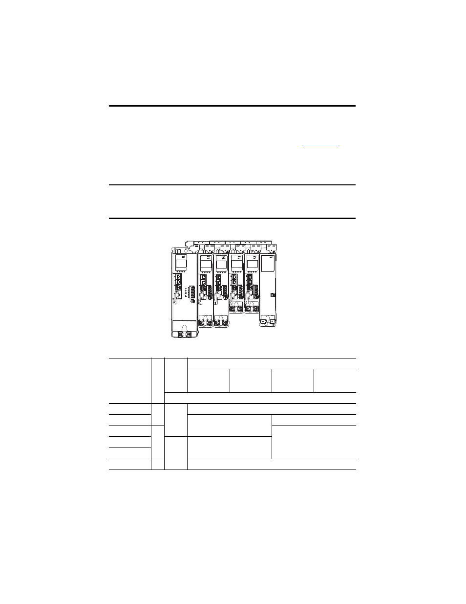
Figure 2 - Kinetix 5500 Drive System Example with Capacitor Module
Table 1 - Capacitor Module Support
The recommended mounting hardware is M4 (#8-32) steel bolts. Apply 2.0 N•m (17.7 lb•in)
maximum torque to each fastener.
IMPORTANT
Mount drives in descending order, left to right, according to frame size with capacitor
modules always mounted on the far right.
The shared-bus connection system is required for capacitor module installations.
Drive Cat. No.
Fram
e S
ize
Standalone
Si
ngle Phase
Ope
ra
ti
on
Three-phase Operation
Standalone
Shared DC
Shared AC/DC
Shared AC/DC
Hybrid
Number of capacitor modules connected, max
2198-H003-ERS
(1)
(1) Catalog number 2198-H003-ERS and any drive in standalone single-phase operation is not compatible with the Kinetix 5500
capacitor module.
1
0
0
2198-H008-ERS
1
2
2198-H015-ERS
2
4
2198-H025-ERS
N/A
3
2198-H040-ERS
2198-H070-ERS
3
4
2198-H
xxx-ERS Drive System
(front view)
Frame 2 Drives
Frame 1 Drives
2198-CAPMOD-1300 Capacitor Module
(optional component)
Shared-bus Connection System
for DC Bus and 24V Control Power
Frame 3 Drive