Important, User interface – Rockwell Automation 42GR Series 9000 LaserSight User Manual
Page 2
2
User Interface
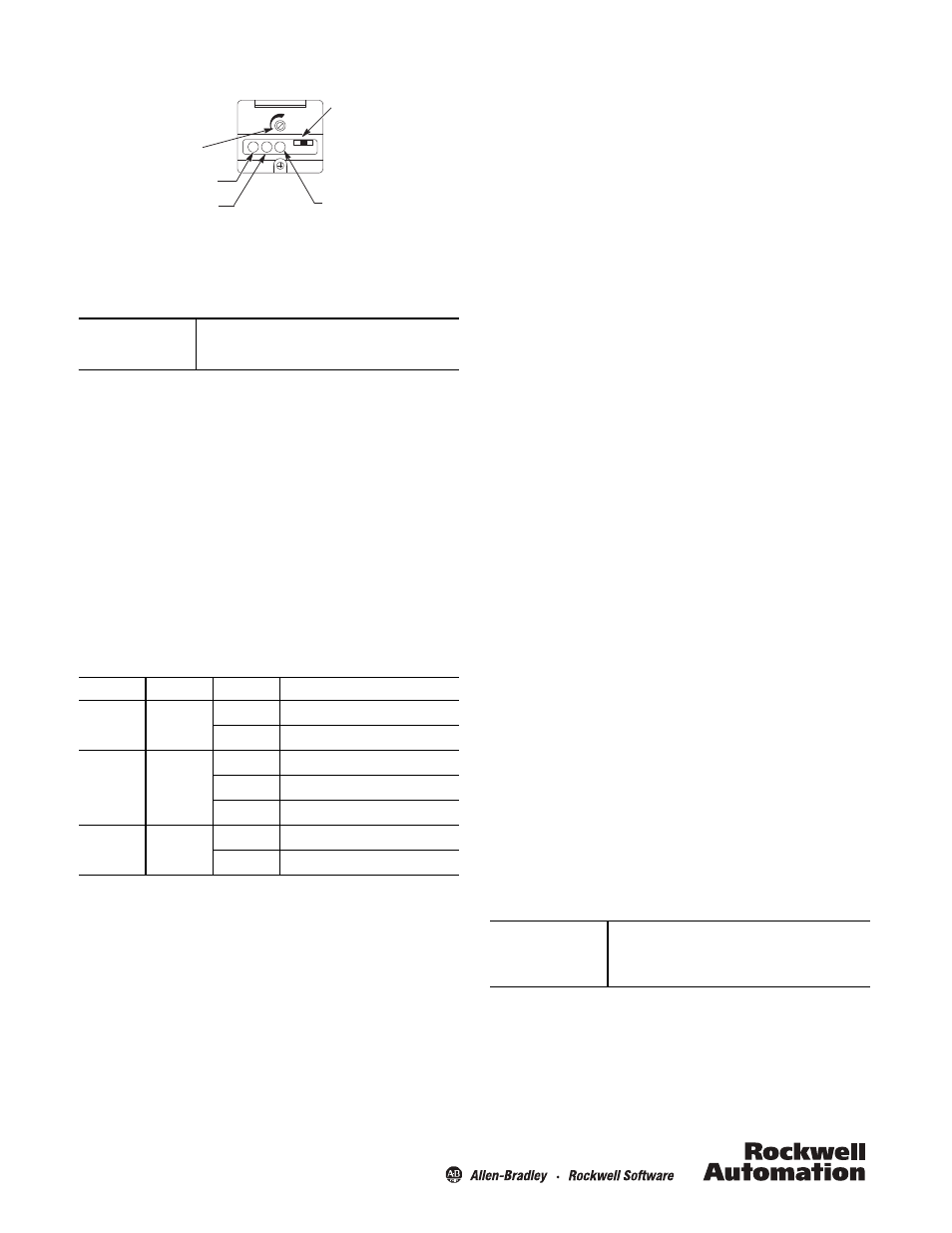
Using a screwdriver, open the top cover of the sensor to access
the user interface panel. This panel contains a single-turn
sensitivity adjustment knob, a two-position mode selector switch,
along with three LED status indicators.
Using a screwdriver, the sensitivity can be increased (clockwise) or
decreased (counterclockwise) to meet the application
requirements. The factory default setting for all versions is
maximum sensitivity.
The LaserSight photoelectric sensor also contains a two-position
selector switch. This switch is used to select either light or dark
operate mode of the sensor. In the light operate mode, the sensor
output will turn ON when the light is being reflected back to the
sensor (reflector for retroreflective, source for transmitted beam
or target for diffuse). In dark operate mode, the sensor output will
turn OFF when no light is being reflected back to it.
After initial sensor configuration, ensure that the
user interface cover is closed tightly to maintain
specified environmental rating!
Status Indicators
Sensor Alignment
The red LED indicator is an alignment aid which indicates that a
margin of 2X has been reached. This means that the sensor is
receiving at least 2 times the signal strength back from the target
needed to trigger an output signal. In general, it is desirable to
have a higher margin to help overcome any deteriorating
environmental conditions, e.g. dust buildup on the sensor's lens.
When aligning the sensor, the best performance can be obtained
if this margin indicator is illuminated with the target in place.
Label
Color
State
Status
Output
Green
OFF
Output de-energized, SCP active
ON
Output energized
Margin
Red
OFF
Margin < 2
ON
Margin > 2
Flashing
Output SCP active
Power
Yellow
OFF
Sensor not powered
ON
Sensor powered
Yellow Power
On Indicator
Green Output
Energized Indicator
Red Margin/
SCP Indicator
Light/Dark
Operate Switch
Sensitivity
Adjustment
IMPORTANT
Damage to the single-turn sensitivity
adjustment knob may occur if turned
beyond min./max. stop points.
Transmitted Beam Models
1. Visually align the emitter and receiver units until the green
output LED turns ON (with light-operate mode) or turns OFF
(with dark-operate mode).
2. To ensure that the beam is centered, it is recommended to
sweep the emitter or receiver in the horizontal and vertical
plane and determine at what position the output indicator
turns ON and then turns OFF. Set the sensor midway between
both positions. The red margin LED should also be ON when
the beam is not broken.
Polarized Retroreflective Models
1. Visually align the sensor on the reflector until the green
output LED turns ON (with light-operate mode) or turns OFF
(with dark-operate mode).
2. To ensure that the beam is centered, it is recommended to
sweep the sensor in the horizontal and vertical plane and
determine at what position the output indicator turns ON and
then turns OFF. Set the sensor midway between both
positions.
3. Break the beam with the object to be detected and check if the
output indicator turns ON (dark-operate mode). If this does
not occur, turn down the sensitivity adjustment until it does.
Restore the light beam by removing the object and check if the
output indicator turns OFF again and the red margin LED comes
ON. If this does not occur, increase the size of the reflector or
decrease the distance between the reflector and the reflector.
Diffuse Models
1. Visually align the sensor on the object until the green output
LED turns ON (with light-operate mode) or turns OFF (with dark-
operate mode).
2. To ensure that the beam is centered, it is recommended to
sweep the sensor in the horizontal and vertical plane and
determine at what position the output indicator turns ON and
then turns OFF. Set the sensor midway between both positions.
3. Remove the object in front of the sensor and eliminate any
background reflection by turning down the sensitivity
adjustment, if such background exists. Replace the object and
verify that the output LED turns ON and the margin LED is ON.
If the sensor continues to detect background reflections by
turning down the sensitivity, it is recommended to eliminate
these reflections by painting with a nonreflective color or to
replace the sensor with a background suppression, sharp cutoff
diffuse or retroreflective sensing mode sensor.
Mounting the Sensor
Securely mount the sensor on a firm, stable surface or support. A
mounting which is subject to excessive vibration or shifting may
cause intermittent operation. Adaptors and mounting brackets
are available for a flexible installation. The sensor is supplied with
the hardware kit 129-130 which contains a plastic mounting nut,
lock washer, 2 M5 x 0.8 x 53 screws and nuts.
Once securely mounted, the sensor may be wired as indicated in
the wiring diagrams.
IMPORTANT
Securely close and tighten the screw on the
user interface cover. Failure to check for a
properly sealed user interface cover may
result in a malfunction or property damage.