Tool path graphic softkeys – Rockwell Automation 8520 9/PC CNC Tool Path Graphics Programming Manual User Manual
Page 8
8 9/PC CNC Tool Path Graphics Programming Manual
Publication 8520-PM097A-EN-P - September 2001
The control continues to plot tool paths, even if the graphics screen is not visible. The actual
display of tool paths is only possible on the graphics screen. When the graphics screen
redisplays, any new tool motions appear on the screen.
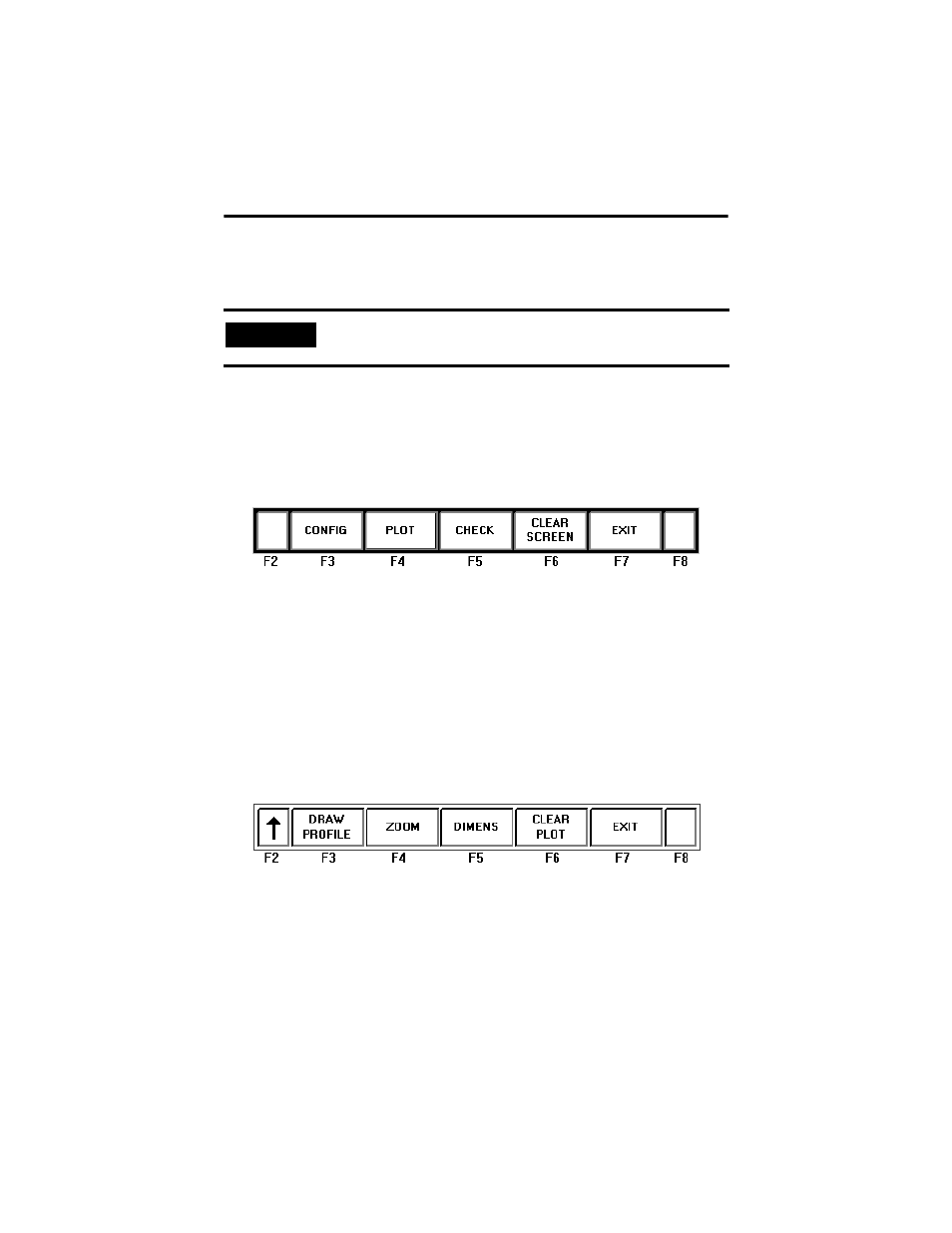
Tool Path Graphic Softkeys
Refer to the following section for an explanation of the softkeys associated with Tool Path
Graphics.
Level 1
CONFIG – Opens a data entry window to set all Tool Path Graphics parameters. This
window also contains revision information.
PLOT – Starts and stops the plotting phase for data acquisition and visualization.
CHECK – Displays the points stored in the local plotting buffer. Selecting this softkey while
you are in 2-D visualization mode activates the checking phase and a second level of softkeys
appear. Refer to the following section entitled, L evel 2.
CLEAR SCREEN – Clears the plotted path from the screen.
EXIT – Allows you to exit the application.
Level 2
Up Arrow – Stops the checking phase and allows you to access the previous softkey menu.
The screen remains unchanged until the user selects the next operation.
DRAW PROFILE – Restores the original set of points stored in the internal buffer after
using the
{ZOOM} softkey. This option is available during the checking phase only.
IMPORTANT
If the graphic screen does not display the tool path you want, you may
need to alter the graphic parameters.