0 mechanical/electrical description, 1 mechanical description, 2 electrical description – Rockwell Automation 61C615 RTD Termination Panel User Manual
Page 9
2Ć1
2.0 MECHANICAL/ELECTRICAL
DESCRIPTION
The following is a description of the termination connectors and the
electrical characteristics of the fieldconnections.
2.1
Mechanical Description
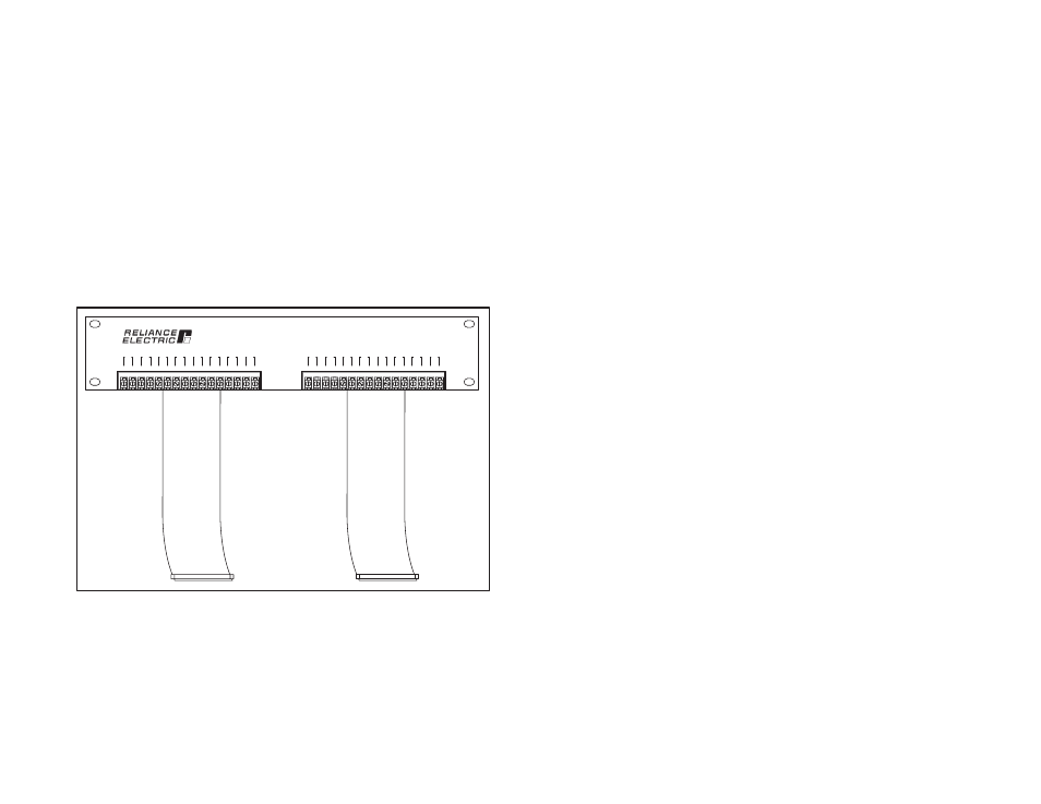
The 61C614 is a 19" rackĆmountable termination panel that includes
two 6Ćfoot, 50Ćwire flat cables. See figure 2.1 for a drawing of the
panel. The panel dimensions are listed in Appendix A.
When the panel is viewedfrom the front, the flat cable on the right
side is for analog inputs 0Ć7 andthe thermocouple coldjunction
compensation. This cable connects to the middle connector on the
61C613. The flat cable on the left side of the termination panel is for
analog inputs 8Ć15. It connects to the bottom connector on the
61C613. The top connector on the 61C613 module is not used. The
termination panel includes 32 screwĆactivated, clamp type barrier
strips for terminating fieldsignals.
61C614
Thermocouple / Analog
Input Termination Panel
+ -
15
+ -
14
+ -
13
+ -
12
+ -
11
+ -
10
+ -
9
+ -
8
+ -
7
+ -
6
+ -
5
+ -
4
+ -
3
+ -
2
+ -
1
+ -
0
Figure 2.1Ć Termination Panel
2.2
Electrical Description
The termination panel is a passive device that provides a
means of transmitting electrical signals from a barrier strip for
fieldsignals to a flat cable that connects to the analog input
module. It also contains a cold junction compensation circuit
(CJC).