0 installation, 1 wiring, 2 initial installation – Rockwell Automation 61C615 RTD Termination Panel User Manual
Page 11
3Ć1
3.0 INSTALLATION
This section describes how to install and remove the termination
panel and its cable assembly.
3.1
Wiring
The installation of wiringshould conform to all applicable codes.
To reduce the possibility of electrical noise interferingwith the proper
operation of the control system, exercise care when installingthe
wiringfrom the system to the external devices. For detailed
recommendations refer to IEEE 518.
3.2
Initial Installation
Use the followingprocedure to install the module:
Step 1.
Turn off power to the system. All power to the rack as well
as all power to the wiringleadingto the termination panel
should be off.
Step 2.
Mount the termination panel. It should be mounted to
permit easy access to the screw terminals on the terminal
board. Make certain that the terminal board is close
enough to the rack so that the cable will reach between
the terminal board and the module. The panel should be
located so that the flat cables can be routed to the front of
the module without coming in contact with high voltage
wires.
Step 3.
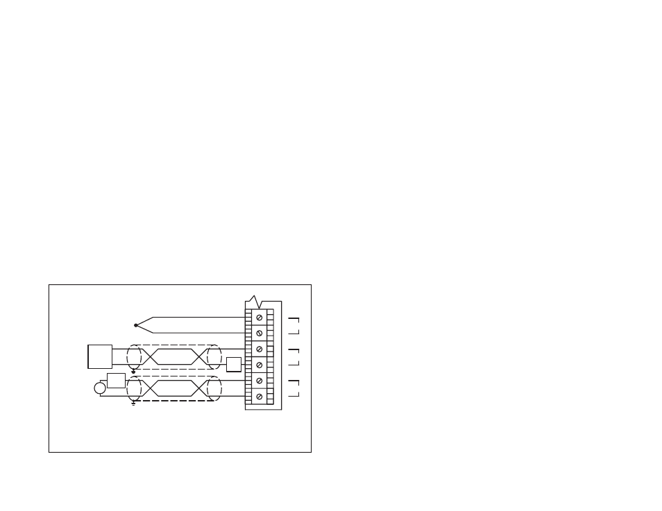
Fasten field wires to the terminal strip. Make certain that all
field wires are securely fastened. Typical field signal
connections are shown in figure 3.1.
+
-
+
-
+
-
+
-
TransĆ
mitter
P/S
XMIT
Voltage
Source
Current
Source
+
-
0
+
-
1
+
-
2
Use 250
W
precision resistor with current source
T/C
Figure 3.1Ć Typical Field Signal Connections