E defining variables in the configuration task, Appendixe, Defining variables in the configuration task – Rockwell Automation 57C400-1 115V AC/DC Input Module User Manual
Page 31: Local i/o definition, Single register reference, Processor module i/omodule, Module in a local rack
EĆ1
AppendixE
Defining Variables in the
Configuration Task
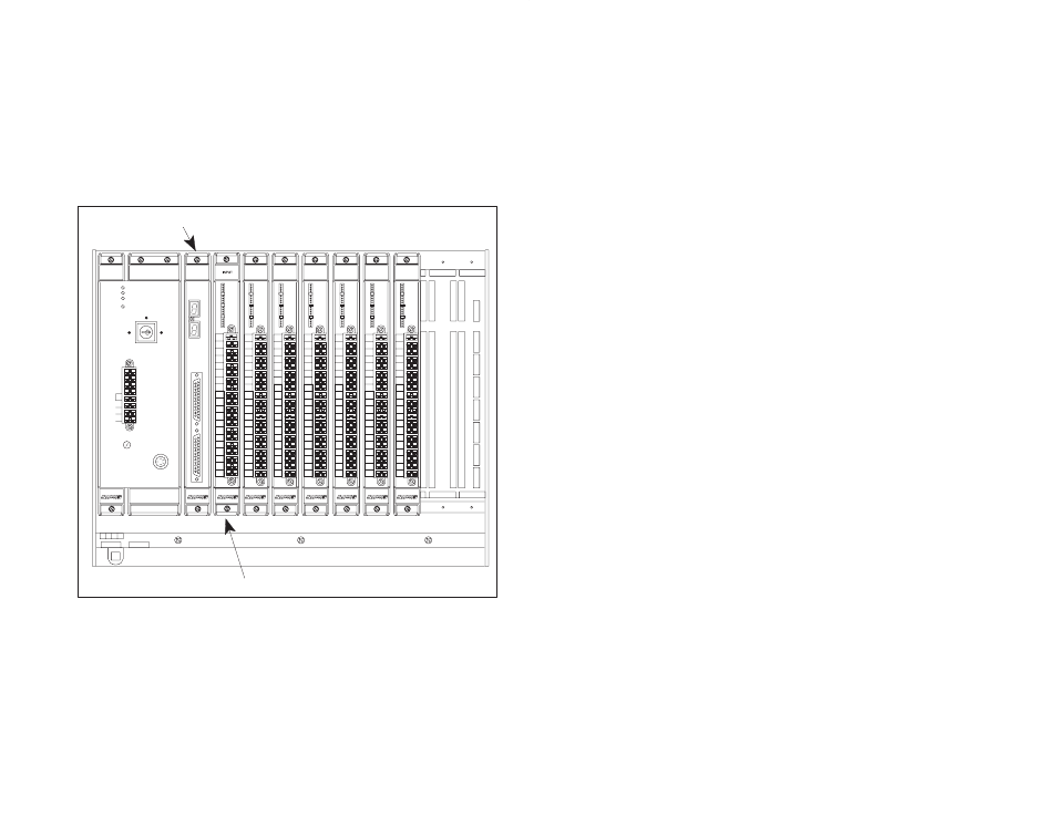
Local I/O Definition
This section describes how to configure the input module when it is located in the
same rack (i.e., the local rack) as the processor module that is referencing it.
Refer to the figure below. Note that this procedure is used only if you are using
the AutoMax Programming Executive software version 2.1 or earlier.
1
0
2
3
4
C1
5
6
7
C2
8
9
10
11
C3
12
13
14
15
C4
B
C
D E
F
G
1
2
3
6
7
8
B
C
D E
F
G
1
2
3
6
7
8
OK
275 W
POWER
SUPPLY
1
0
2
3
4
C1
5
6
7
C2
8
9
10
11
C3
12
13
14
15
C4
B
C
D E
F
G
1
2
3
6
7
8
1
0
2
3
4
C1
5
6
7
C2
8
9
10
11
C3
12
13
14
15
C4
B
C
D E
F
G
1
2
3
6
7
8
1
0
2
3
4
C1
5
6
7
C2
8
9
10
11
C3
12
13
14
15
C4
B
C
D E
F
G
1
2
3
6
7
8
120V
LINK
GND
L2
L1
FUSE
BATTERY
BACKĆUP
POWER ON
P S READY
SYSTEM READY
BLOWN FUSE
NORMAL
REMOTE
PROGRAM
57491
Processor Module
I/OModule
B
C
D E
F
G
1
2
3
6
7
8
1
0
2
3
4
C1
5
6
7
C2
8
9
10
11
C3
12
13
14
15
C4
B
C
D E
F
G
1
2
3
6
7
8
1
0
2
3
4
C1
5
6
7
C2
8
9
10
11
C3
12
13
14
15
C4
B
C
D E
F
G
1
2
3
6
7
8
0
1
2
3
4
5
6
7
8
9
10
11
12
13
14
15
1
0
2
3
4
C1
5
6
7
C2
8
9
10
11
C3
12
13
14
15
C4
0
1
2
3
4
5
6
7
8
9
10
11
12
13
14
15
0
1
2
3
4
5
6
7
8
9
10
11
12
13
14
15
0
1
2
3
4
5
6
7
8
9
10
11
12
13
14
15
0
1
2
3
4
5
6
7
8
9
10
11
12
13
14
15
0
1
2
3
4
5
6
7
8
9
10
11
12
13
14
15
0
1
2
3
4
5
6
7
8
9
10
11
12
13
14
15
Module in a Local Rack
Single Register Reference
Use the following method to reference all 16 inputs as a single register. Only one
statement is necessary in the configuration task for the entire module. The
symbolic name of the register should be as meaningful as possible:
nnnnn IODEF SYMBOLIC_NAME%[ SLOT=s, REGISTER=0]