Rockwell Automation 57C442 Data Highway Plus Interface Module User Manual
Page 32
4-14
05 REM
The variables that follow define
&
parameters for the
&
GATEWAY CMD OK@ function
10 COMMON B3BASE% \!
Represents the physical address of
&
starting register on the Data Highway &
Plus module to be read from
20 LOCAL DST%
\!
The address of the bridge node on
&
the local Data Highway Plus network
21 LOCAL STS%
\!
The location where the status
&
resulting from the operation is stored
22 LOCAL SZE%
\!
The number of registers to be
&
transferred
23 LOCAL CMD%
\!
The Data Highway Plus command
&
sent by the module
30 DST% = 34
31 STS% = 0
32 SZE% = 100
33 CMD% = 3
40 IF NOT GATEWAY_CMD_OK@(STS%, CMD%, DST%,
&
“!01.24.00.00.84.00.80.00.00.14.00.00.N7:0”, &
VARPTR! (B3BASE%), SZE%) THEN 20000 \! process errors
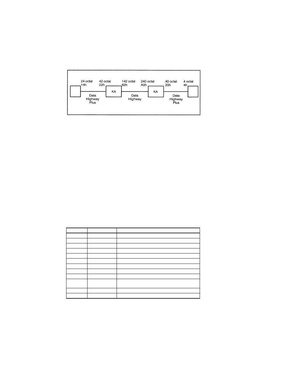
In the example above, the routing bytes were determined as
follows.Recall that the last item in the actual ”slave_reg” parameter is
the destination file address.
Byte
Value Meaning
1
LSAP
01 for a 1785-KA bridge
2
24h
3
DID_LO
00 for a 1785-KA bridge
4
DID_Hl
00 for a 1785-KA bridge
5
DNDE_LO
84h (see below)
6
DNDE_Hl
00 for a 1785-KA bridge
7
LIFETIME
80h for a1785-KA bridge
8
SID_LO
00 for a 1785-KA bridge
9
SID_HI
00 for a 1785-KA bridge
10
SNDE_HI
14h is the station number of the Data Highway
Plus module
11
SNDE_LO
00 for a 1785-KA bridge
12
NSAP
00 for a 1785-KA bridge