Indicators, About the mounting kit – Rockwell Automation 1797-CEC FLEX Ex Bus Isolator and Flexbus Connector User Manual
Page 17
FLEX Ex Bus Isolator and Flexbus Connector 17
Publication
1797-5.13 - June 2010
2. Strip the +V and -V wires to a length so no bare conductor shows
after inserting the wires into position (+V, -V).
3. If you are using the spring terminals of the plug, insert a screwdriver
into the slot and carefully pry until the spring clamp opens to accept
the wire.
4. Connect either a 1797-TB3 terminal base, a 1794-CE1 cable, or a
1794-CE3 cable onto the FLEX Ex backplane connector of the
1797-BIC module.
Indicators
The 1797-BIC isolator module provides a power indicator to show power has
been applied to the module.
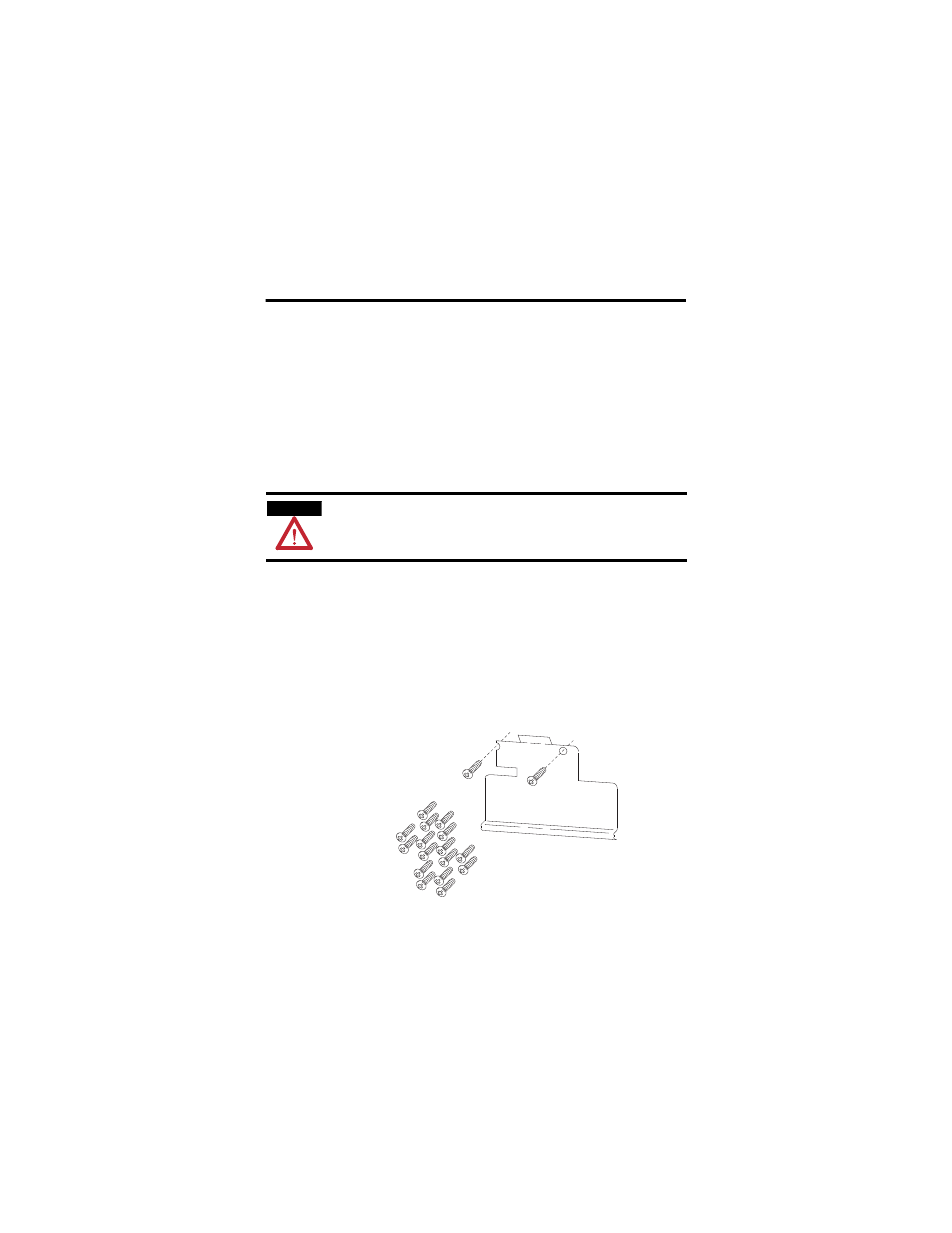
About the Mounting Kit
Use the optional 1794-NM1 mounting kit to mount your system on a panel or
wall without a DIN rail.
ATTENTION
The FLEX Ex backplane connector cover must remain in place until a
FLEX Ex terminal base or cable is connected to the 1797-BIC module.
1794-NM1
Mounting Kit with
18 screws (2 screws for the
adapter and 2 screws for
each module).
30238