Removing an air flow switch pcb, Installing an air flow switch pcb – Rockwell Automation 2364E INST Air Flow Switch PCB and Pwr Sup Replacement User Manual
Page 3
Air Flow Switch PCB and Power Supply Replacement
3
Publication 2300-5.12 - April 1998
Removing an Air Flow Switch PCB
Follow this procedure to remove an air flow switch PCB:
1. Remove all Lexan™ guards that shield the PCB.
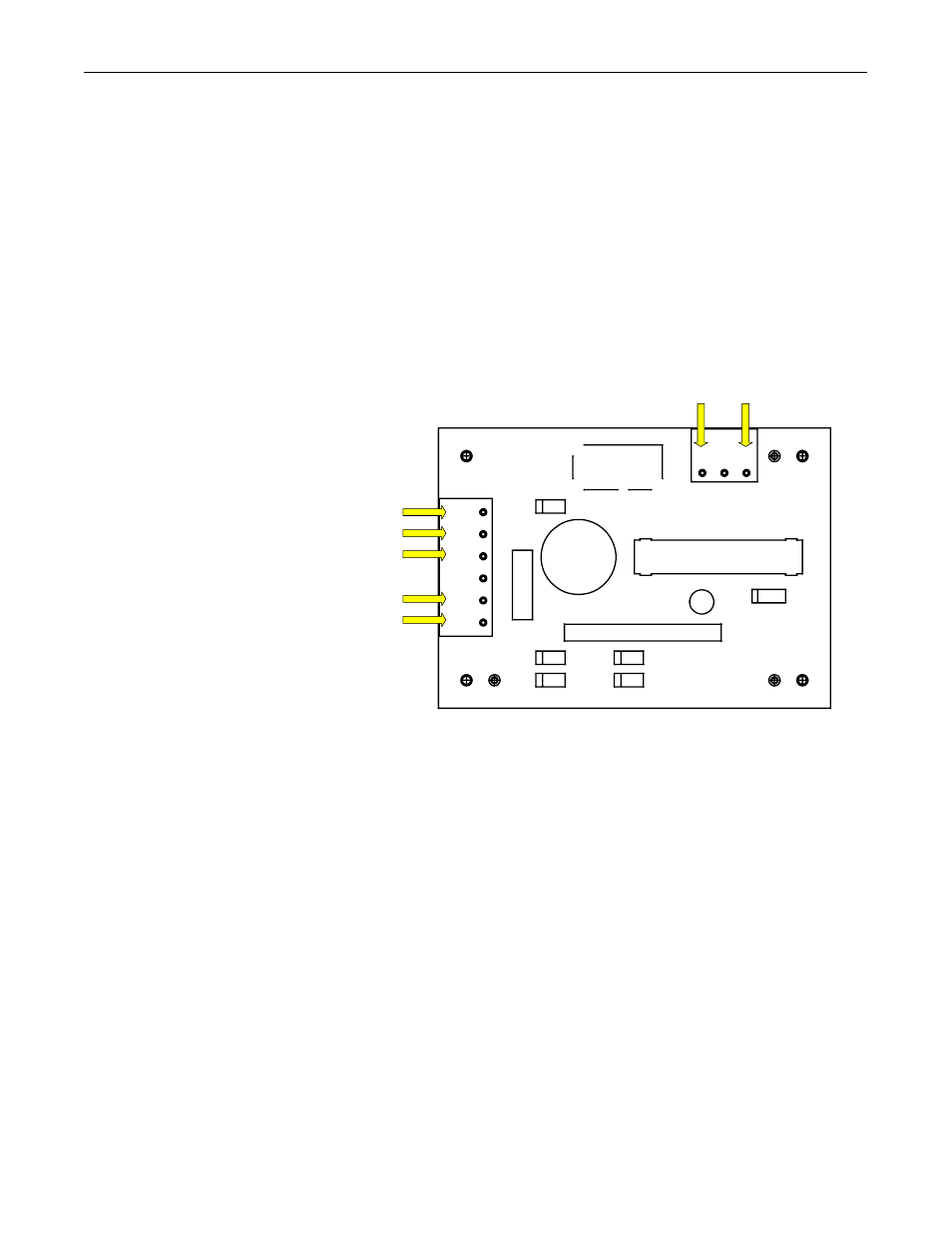
2. Disconnect where shown in Figure 1:
•
the input power wiring
•
the output contact wiring
•
the air flow sensor wiring
Figure 1
Air Flow Switch PCB
3. Remove the PCB from the 4 plastic standoffs.
4. Remove the air flow switch PCB.
Installing an Air Flow Switch PCB
Follow this procedure to install an air flow switch PCB:
1. Put the air flow switch PCB in place.
2. Secure the air flow switch PCB to the standoffs.
3. Connect and verify:
•
the input power wiring
•
the output contact wiring
•
the air flow sensor wiring
4. Replace any Lexan guards that you removed.
5. Dispose of the removed part according to your company’s proce-
dures and local ordinances.
1
1
2
3
4
5
6
2
3
SIG
+5V
IN1
IN2
NO1
NO2
BARCODE
COM