Rockwell Automation 57C409 2 Channel Analog Input Module User Manual
Page 14
3Ć2
Step 4.
Take the module out of its shipping container. Take it out of
the antiĆstatic bag, being careful not to touch the
connectors on the back of the module.
Step 5.
Insert the module into the desired slot in the rack. The
module will work only in a rack that contains a processor
module. Do not attempt to use the module in a remote
rack. Use a screwdriver to secure the module into the slot.
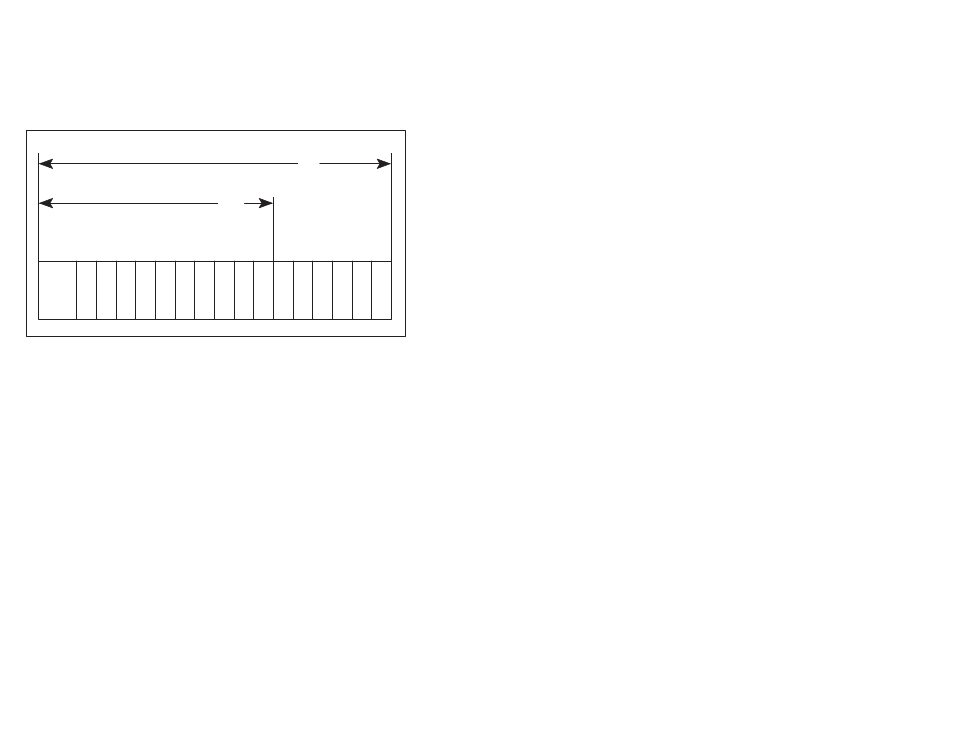
Refer to figure 3.2.
P/S
0
1
2
3
4
5
6
7
8
9 10 11 12 13 14 15
10
Typical 10 Slot Rack
16
Typical 16 Slot Rack
Figure 3.2 Ć Rack Slot Numbers
Step 6.
Attach the field terminal connector (M/N 57C371) to the
mating half on the module. Make certain that the
connector is the proper one for this module. Use a
screwdriver to secure the connector to the module.
Note that both the module and the terminal strip connector
are equipped with keys." These keys should be used to
prevent the wrong cable from being connected to a
module in the event that the connector needs to be
removed for any reason and then reattached later.
At the time of installation, rotate the keys on the module
and the connector so that they can be connected together
securely. It is recommended that, for modules so
equipped, the keys on each successive module in the
rack be rotated one position to the right of the keys on the
preceeding module.
If you use this method, the keys on a particular connector
will be positioned in such a way as to fit together only with
a specific module, and there will be little chance of the
wrong connector being attached to a module.
Step 7.
Turn on power to the rack.
Step 8.
Verify the installation by connecting the programming
terminal to the system and running the ReSource
software. Use the I/O MONITOR function.
Set registers 7 and 8 to the value 1.