Rockwell Automation 2090-CSBM1DF-10AF Single Motor Cables with Circular DIN Connector Type 740 Install Instructions User Manual
Page 2
2 Single Motor Cables with Circular DIN Connector Type 740
Rockwell Automation Publication 2090-IN049A-EN-P - October 2013
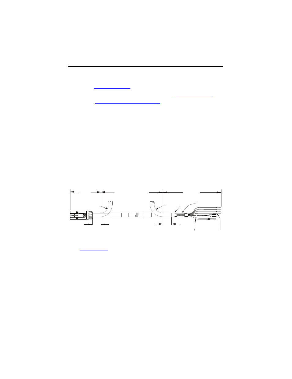
Follow these guidelines when installing a single motor cable:
•
Do not bend the cable within 76.2 mm (3.0 in.) of the connector or the flying-lead end.
See the
Installation Guidelines
illustration.
•
Do not exceed the bend radius limitation specified in the
.
•
Refer to
Cable Pinouts and Schematics on page 3
to identify each wire and its respective
drive connection.
•
Remove and discard the protective sleeve from the data signal wires shortly before you
install these wires on the feedback connector kit.
•
Connect unused brake conductors to the drive to prevent accidental contact.
For continuous-flex cables, follow these additional installation requirements:
•
The continuous-flex zone is the area where the cable can repeatedly flex up to its
specified bend radius.
•
Installation areas require rigid mounting to prevent the cable from flexing where it
connects to other components.
Installation Guidelines
Continuous-flex Zone
Installation
Area
Installation
Area
Signal
Labels
Exposed Shield
Shrink
Wrap
for recommended
continuous-flex zone radius values.
Insulated and
Shielded
Twisted Pair
2090-CSBM1DF-10AF
xx cable shown.
76.2 mm
(3.0 in.)
76.2 mm
(3.0 in.)
Bend
Radius
Bend Radius