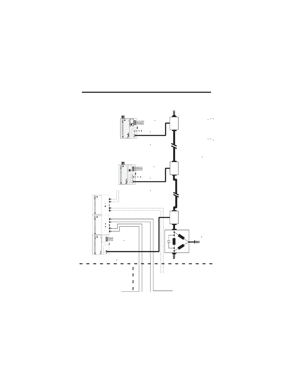
Cenelec controlnet ex system diagram, No de 1 – Rockwell Automation 1797-RPFM ControlNet Ex Modular Repeater Adapter Fiber Repeater Module User Manual
Page 19
ControlNet Ex Modular Repeater Adapter & Fiber Repeater Module 19
Publication
1797-5.15 - June 2010
CENELEC ControlNet Ex System Diagram
1
.
.
.
.
.
C
N
et Ex
trk trm
306
70CE
Co
nt
ro
lN
et
E
x
ta
p
Safe Area
Haza
rd
ous Area
Zone
0
No
de
1
Co
nt
ro
lN
et
E
x
ta
p
Co
nt
ro
lN
et
E
x
ta
p
Co
nt
ro
lN
et
E
x t
ap
C
N
et Ex
tap
trm
Ci
<68 pF
Li
negl
.
Ch
B
U
o=5.
4V
,
Io=160
mA
,
F
-3
>5
00 kH
z
Fl
exbus
U
o=5.
4V
,
Io=40
0 mA
,
Po=2.
16 W
,
Co=
65
F,
Lo=
10
H
Ch
0
fi
be
r
The C
oax T
runk Ca
ble
is p
er
m
it
ted t
o hav
e a min
imum l
engt
h o
f 1
,00
0m wit
h on
ly 2
connect
ed
Cont
ro
lN
et
Ex
Ta
ps
d
rop
pin
g
to
onl
y 250m wit
h t
he maximum al
lo
w
ed
connect
ed
C
ont
ro
lN
et
Ex
Ta
ps
of
48.
N
ode 4 ..
. 48
No
de 3
Th
e
C
ont
ro
lN
et
Ex Sys
te
m
is
an i
nt
ri
nsi
cal
ly
saf
e syst
em accor
di
ng t
o EN
50
039.
W
hen i
nst
al
ling t
he syst
em,
t
he
cer
ti
fi
cat
e of
c
onf
or
mit
y and t
he nat
io
nal
in
st
al
lat
ion r
egul
at
io
ns m
ust
be hee
ded.
T
he compone
nt
s
of
t
he
C
ont
ro
lN
et
Ex s
yst
em an
d t
he
in
te
rc
onne
ct
ion
s ar
e
shown
on
t
he
in
st
all
at
ion
dr
awing
(A
-B
Pu
b.
179
7-
6.5
.6)
.
For
t
he t
ran
smit
ta
l be
tw
ee
n
th
e
saf
e ar
ea and
t
he hazar
do
us ar
ea onl
y
op
ti
cal
g
las
s-
fi
ber
s ar
e
pe
rm
it
ted.
Th
e
di
amet
er
of
a si
ngl
e
gl
as
s-
fi
ber
m
ust
be
>6
um. The power
dens
it
y of
t
he t
ransmi
tt
er
dio
de must
be
<5
m
W
/mm
2
.
Pr
ot
ect
t
he syst
em
agai
nst
el
ect
ro
st
at
ic
ch
ar
ge.
Po
st
a si
gn near
t
he
mai
n compon
ent
s
of
t
he syst
em:
A
tt
ent
io
n!
A
vo
id el
ect
ro
st
at
ic cha
rg
e.
1797
-A
CNR15/
* or
RSD-
GW
-E
x2
.CN
1797
-ACNR15/
* or
RSD-GW
-Ex2.CN
Fle
xbus
Uo
=5
.4
V,
Io
=400 mA
,
Po=
2.1
6 W
,
C
o=65
F,
Lo=1
0
H
Po
wer
S
uppl
y
U
i=9.
5V
,
Ii=
1 A,
Ci
=<
120 nF
,
Li
=negl
ig
ib
le
Ch
A
U
o=5
.4V
,
Io=1
60 mA
,
F
-3
>500
kH
z
Power
S
uppl
y
Ui
=9
.5
V,
Ii=1
A,
Ci
=<
120 nF
,
Li
=neg
ligi
ble
Ch
B
U
o=5.
4V
,
Io=160
mA
,
F
-3
>5
00kH
z
Ch
A
U
o=5
.4V
,
Io=1
60 mA
,
F
-3
>500 kH
z
75
O
hm
1W
C
i negl
.
Li
n
egl
.
The ambi
ent
t
empe
ra
tu
re
r
ang
e
of
t
he Con
tr
ol
N
et
Ex syst
em i
s -
20 t
o
+70
o
C.
N
ea
r t
he mai
n
co
m
ponent
s of
t
he
sys
te
m
a pl
at
e
wi
th
t
he
syst
em mar
ki
ng
mu
st
be at
ta
ched
. I
f
th
e
sy
st
em
is
in
st
al
le
d
in
a cabi
net
t
he
pl
at
e must
b
e
fi
xed on t
he insi
de of
t
he
cabi
net
d
oor
.
*R
G
6-
C
N
et
is
def
ined
as:
C
ab
le
Im
pedan
ce=75
O
hm +
or
-
3 O
hm
Ca
ble
C
apaci
tance<
6nF per
1
00 m
Ca
ble
R
esis
ta
nce>9.
08
O
hm pe
r
100
m
Ca
ble
A
tt
enuat
ion
(-
20t
o+
70
o
C)
0.
2 MH
z >
0.
93 dB/100
m
5 MH
z
> 1.
39 dB/10
0
m
0.
5 MH
z >
0.
95
dB/100
m
10
MH
z >
1.8
6 d
B
/100
m
1 MH
z
>
1.
07
dB/10
0 m
20
MH
z >
2.
73 dB
/1
00 m
coax t
runk cabl
e
coax t
runk cabl
e
Cab
le t
ype 1189
A
,
309
2A
, or
3092A
Bl
ue
fr
om manuf
act
ur
er
Be
lde
n W
ir
e
or
t
ype
RG
6-
CN
et
*
CNet Ex
tr
k tr
m
75
O
hm
1W
C
i negl
.
Li
n
egl
.
Ci
<
60
pF
Li
<
56
0 n
H
Li
<
11
00
uH
Li
<
110
0 u
H
N
ode
2
17
97
-RP
A
/* o
r
RS
D-C
FA
-Ex
.C
N
17
97
-R
PF
M
/* or
RSD
-F
C-E
x2
.CN
3k
m
17
97
-R
PF
M/
* or
RSD
-F
C-E
x2
.C
N
3
km
Ch
0
fi
be
r
Ch
1
fi
be
r
Ch
1
fi
be
r
Po
w
er
S
upp
ly
U
i=9.
5V
,
Ii=1 A
,
Ci
=<
12
0 n
F,
Li=n
egl
igi
bl
e
U
o=5.
4V
,
Io
=201 mA
,
F
-3
>5
00 kH
z
Haz
a
rdous Area
Zon
e 0