Rockwell Automation 2030-RLS_ _D Dual Remote Lockout Station User Manual
Page 3
IMPORTANT:
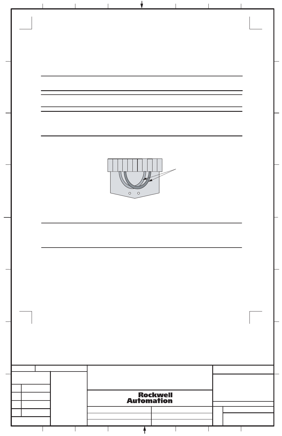
Connector plugs provided on ElectroGuard® Control Modules and Expansion Modules are factory shipped with two
jumper wires installed (see Figure 4).
These two jumper wires must be removed and discarded when wiring to connect a Remote Lockout Station to the connector plug.
Failure to remove the two jumper wires prevents proper operation of the RLS "System Isolated" indicator light.
---------------
----------
----------
----------
---------------
---------------
DUAL REMOTE LOCKOUT STATION
INSTALLATION INSTRUCTION SHEET
IMPORTANT: When installing and wiring the Dual RLS, remove and discard both red plastic cap plugs. If wiring the Dual RLS using one or
both top openings, remove the corresponding closing plug(s) from the top and install in the open bottom hole(s) to maintain the integrity of the
enclosure environmental rating.
IMPORTANT:
The cables to the Dual RLS must not be run in a line voltage wireway or run adjacent to power conductors. The cables
must be protected from physical damage. This requires the appropriate conduit outside of the Dual RLS.
3
4
1
1013449
42052-125
OF
N/A
N/A
N/A
REVISION
AUTHORIZATION
DR.
CHKD.
APPD.
DATE
DATE
DATE
E - DOC
LOCATION: MILWAUKEE, WISCONSIN U.S.A.
B-vertical.ai
DWG.
SIZE
SHEET
B
1
2
3
4
5
6
7
8
A
B
C
D
E
F
G
H
REFERENCE
DIMENSIONS APPLY BEFORE
SURFACE TREATMENT
(DIMENSIONS IN INCHES)
TOLERANCES UNLESS
OTHERWISE SPECIFIED
.XX:
.XXX:
ANGLES:
42052
Remote Lockout Station Cable Specifications (Cont'd)
2. Use appropriate environmentally-rated hubs or conduit fittings to connect cables to the Dual RLS enclosure.
Each Dual RLS is furnished with four 1.38 in. (35mm) diameter openings (two on the top and two on the bottom) designed to accept 1 in.
(25.4 mm) conduit fittings or hubs.
Figure 4
RLS Connector Plug Jumper Wire
RLS Connector Plug
1 2 3 4 5 6 7 8 9 10 11
3. Select an RLS port and connector plug on both ElectroGuard® units to be dedicated to the Dual RLS being installed.
Remove these plugs by firmly grasping their strain relief tabs and pulling straight out from the port.
IMPORTANT:
Control Module and Expansion Module connector plugs and ports, with the exclusion of the HV connector in the
Control Module, are factory keyed. This is done to ensure correct plug installation after maintenance or servicing which may have
required the removal of any of the connector plugs.
Installing an RLS connector plug into a port with non-matching keying may damage the connector as well as the Control Module or
Expansion Module port.
Factory installed jumper wires. These
two wires MUST be removed when
wiring an RLS to the connector plug
(3)
THIS DRAWING IS THE PROPERTY OF
ROCKWELL AUTOMATION, INC.
OR ITS SUBSIDIARIES AND MAY NOT BE COPIED,
USED OR DISCLOSED FOR ANY PURPOSE
EXCEPT AS AUTHORIZED IN WRITING BY
ROCKWELL AUTOMATION, INC.