E - doc – Rockwell Automation 2030-RLS_ _D Dual Remote Lockout Station User Manual
Page 2
IMPORTANT: The maximum total cable length between all of the RLSs and the Control Module in the ElectroGuard® Power Panel shown in
Table 2 must not be exceeded. This may affect the reliable operation of the ElectroGuard®. Consider using an optional Expansion Module if cable
lengths greater than those shown are needed (see Installation and Wiring of the Expansion Module in Chapter 2 of the ElectroGuard® User Manual
Revision 2030-UM003A-EN-P or later).
1
1013449
42052-125
OF
N/A
N/A
N/A
REVISION
AUTHORIZATION
DR.
CHKD.
APPD.
DATE
DATE
DATE
E - DOC
LOCATION: MILWAUKEE, WISCONSIN U.S.A.
B-vertical.ai
DWG.
SIZE
SHEET
B
1
2
3
4
5
6
7
8
A
B
C
D
E
F
G
H
REFERENCE
DIMENSIONS APPLY BEFORE
SURFACE TREATMENT
(DIMENSIONS IN INCHES)
TOLERANCES UNLESS
OTHERWISE SPECIFIED
.XX:
.XXX:
ANGLES:
42052
---------------
----------
----------
----------
---------------
---------------
2
4
DUAL REMOTE LOCKOUT STATION
INSTALLATION INSTRUCTION SHEET
The cable lengths in Table 2 represent the total wire impedance allowed to help ensure proper operation of the safety monitoring relays
used in the isolation system. See Appendix C of the ElectroGuard® User Manual regarding length calculation, conductor sizing and
installation scenarios. Note that each Dual RLS is connected to two separate ElectroGuard® units, and a cable length calculation must
be done for both systems separately. When doing individual calculations, use only the length of the cable connected directly to that unit.
Wiring the Dual Remote Lockout Station
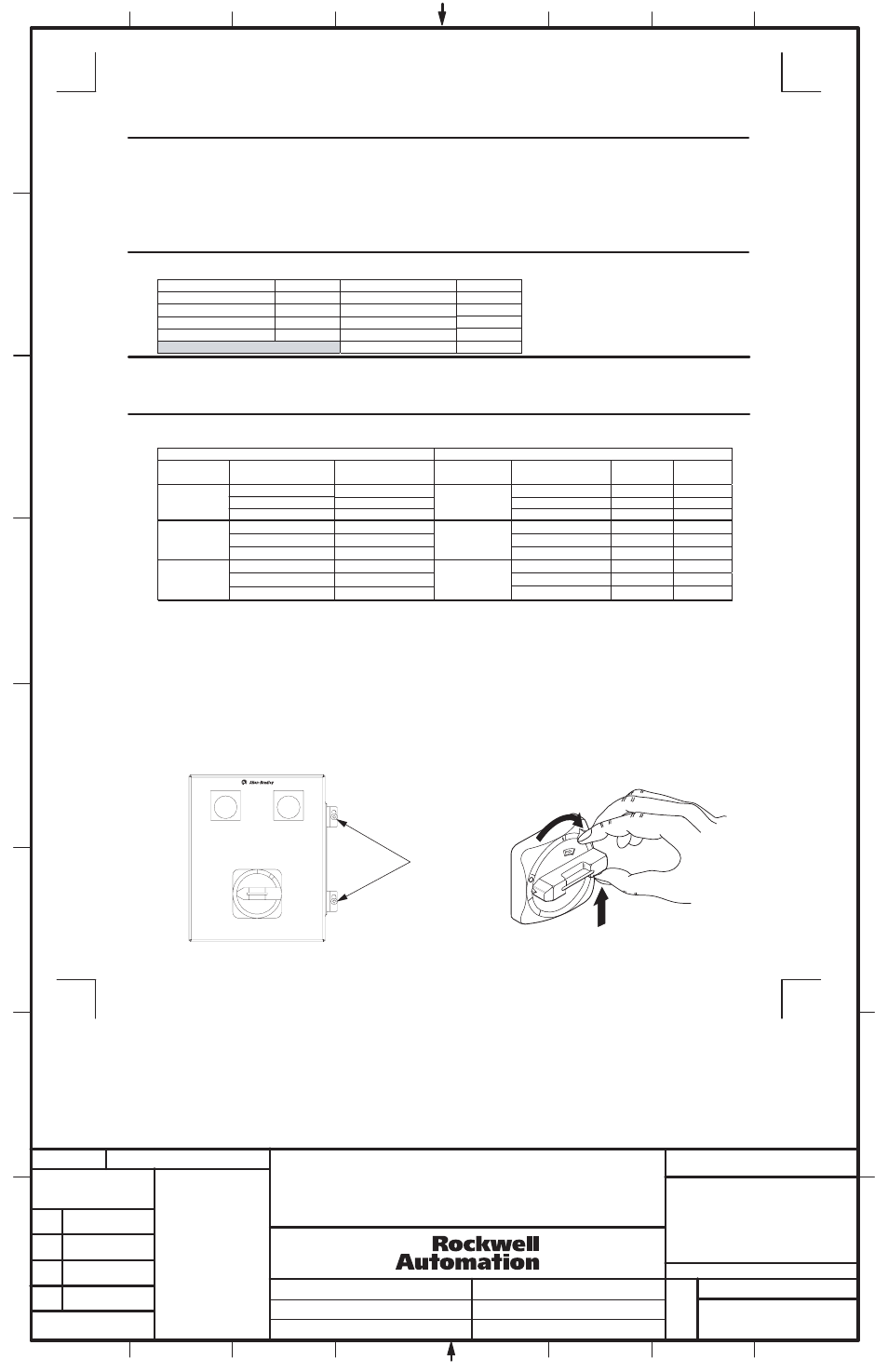
1. Open the RLS enclosure by loosening the two cover clamp screws (See Figure 2).
With the opearting handle held in the OFF position, squeeze the interlock lever and the operation handle held as in Figure 3. Lift the
cover away from the base.
Figure 2
Loosening the Dual RLS Cover Clamp
Figure 3
Operating Interlock Lever to Open Dual RLS
Enclosure
Table 1
Suggested Color Scheme for Remote Lockout Station Cable
Remote Lockout Station Cable Specifications
RLS Terminal Block No.
Wire Color
RLS Terminal Block No.
Wire Color
1 Black
6
Yellow
2 Red
7
Brown
3 Blue
8
Violet
4 Orange
9
Gray
GND
Green
Table 2
Maximum Allowable Cable Lengths
In North America
Outside of North America
Wire
Gauge
Control Module
Connector
Maximum Total
Cable Length (ft.)
Wire
Gauge (mm
2
)
Maximum Total
Cable Length (m)
RLS1,
RLS1, RLS2, RLS3, RLS4
RLS1, RLS2, RLS3, RLS4
RLS1, RLS2, RLS3, RLS4
RLS2, RLS3
19,500
19,500
19,500
5,900
23A-85A
110A-1200A
X
---
---
---
---
---
---
X
X
X
X
X
---
X
5,900
14 AWG
RLS4, RLS5, RLS6
2.1
5,900
RLS1, RLS2, RLS3
12,250
12,250
12,250
3,735
3,735
16 AWG
RLS4, RLS5, RLS6
1.3
3,735
RLS1, RLS2, RLS3
7,650
7,650
7,650
2,330
2,330
18 AWG
RLS4, RLS5, RLS6
0.8
2,330
N
O
F
O
F
Cover
Clamp
Screws
SYSTEM ISOLATED
SYSTEM ISOLATED
(2)
THIS DRAWING IS THE PROPERTY OF
ROCKWELL AUTOMATION, INC.
OR ITS SUBSIDIARIES AND MAY NOT BE COPIED,
USED OR DISCLOSED FOR ANY PURPOSE
EXCEPT AS AUTHORIZED IN WRITING BY
ROCKWELL AUTOMATION, INC.
IMPORTANT:
·
Cable must have copper conductors only
.
·
Cable with 600V insulation is required.
·
Oil resistant cable is recommended.
·
Individual conductors within the cable should be color-coded or otherwise clear
ly marked (see Table 1).
·
Cable must have a shield with a drain wire Similar to: ALPHA wire X
TRA-GUARD® 2:
- Part No. 25450/9 for #14 AWG, 0.64" O.D.
- Part No. 25440/9 for #16 AWG, 0.61" O.D.
- Part No. 25430/9 for #18 AWG, 0.55" O.D.
---
X
---
X