Installation in zone 1 – Rockwell Automation 1797-IJ2 FLEX Ex Frequency Input Module User Manual
Page 4
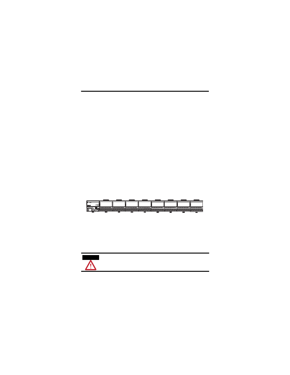
4 FLEX Ex Frequency Input Module
Publication
1797-5.9 - June 2010
1. Rotate keyswitch (1) on terminal base unit (2) clockwise to position 1 as
required for this type of module.
Do not change the position of the keyswitch after wiring the
terminal base unit.
2. Make certain the flexbus connector (3) is pushed all the way to the left to
connect with the neighboring terminal base/adapter.
You cannot install the module unless the connector is fully
extended.
3. Make sure the pins on the bottom of the module are straight so they will
align properly with the connector in the terminal base unit.
4. Position the module (4) with its alignment bar (5) aligned with the groove
(6) on the terminal base.
5. Press firmly and evenly to seat the module in the terminal base unit. The
module is seated when the latching mechanism (7) is locked into the
module.
6. Make certain that you only connect terminal base units to other
intrinsically safe system modules or adapters to maintain the integrity of
the intrinsically-safe backplane.
7. Remove cap plug (8) and attach another intrinsically safe terminal base
unit to the right of this terminal base unit if required.
Installation in Zone 1
This module must not be exposed to the environment. Provide a suitable
metal enclosure. This module has a protection factor of IP20.
ATTENTION
This module cannot be used in an intrinsically safe
environment after it has been exposed to non-intrinsically
safe signals.
20128-M